
User manual


12 GMC-I Messtechnik GmbH
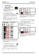
7.2.2 Simulation of PE to phase
➭ Set the bottom rotary selector switch
(S2) to the PE-U
EXT
position.
* The test object’s correct reaction to the simulat-
ed fault can be found in the manufacturer’s op-
erating instructions.
➭ Step 18: see section entitled “Protective
Conductor Current Measurement (I
PE
) at
Mode 2 Charging Cable” on page 9.
Step
Rotary
Switch
Tes t Adapter
ICCB-
IN1
Action
L1
LED
L2
LED
L3
LED
N
LED
PE
LED
LED
11
*
PROFITEST⏐EMOBILITY Fault Simulation