
User manual


GMC-I Messtechnik GmbH 11
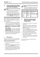
7.2 Mode 2 Charging Cable
(single-phase)
➭ Switch mains voltage on by
turning the top rotary selector switch (S1)
to the Status C position (system state: ve-
hicle ready for charging).
7.2.1 Simulated Interruption
➭ Start with the bottom rotary selec-
tor switch (S2) in the first ON position in
the green area for single-phase interrup-
tion.
➭ Switch through the positions, one after
the other, in the clockwise direction (ta-
ble from top to bottom).
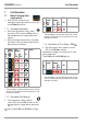
Conductor Interruption Using a 3-Phase, Mode 3 Charging Cable as an Example
* The test object’s correct reaction to the simulat-
ed fault can be found in the manufacturer’s op-
erating instructions.
Regarding step 8: The N LED also lights up due to star connection, although N is interrupted!
Note!
Tripping performance may deviate from
this example in the case of ICCBs from
other manufacturers – adhere to the
manufacturer’s test instructions!
Step
Rotary
Switch
Test Adapter
ICCB
Action
L1
LED
L2
LED
L3
LED
N
LED
PE
LED
LED
1
*
2
3
4
5
6
7
8
9
10
PROFITEST⏐EMOBILITY Fault Simulation