
User manual

GMC-I Messtechnik GmbH 7
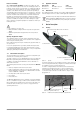
3.4 Automatic Evaluation of Measured Impedance
Automatic evaluation is only possible with the detailed representa-
tion.
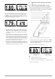
• Protective device parameters are stored to memory or to the
database. Type, nominal current In and disconnection time ta
appear at the top of the display (see example in figure 2.5).
After pressing the T
A
key for the first time, disconnection time
ta and the smallest short-circuit current IFmin required for
shutdown appear at the bottom of the display.
• Another protective device type and nominal current can be
selected immediately after activating the T
A
key by pressing
and holding the DISP
▲ or DISP ▼ key. After selection, wait
about 5 seconds, after which the initial status for voltage mea-
surement is displayed.
• Another disconnection time can be selected immediately after
activating the T
A
key by pressing the T
A
key once again. After
selection, wait about 5 seconds, after which the initial status
for voltage measurement is displayed.
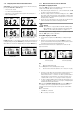
• If the symbol is displayed along with the results of the
impedance measurement after its completion, short-circuit
current calculated from impedance is greater than the mini-
mum short-circuit current required for triggering the selected
protective device.
However, if calculated short-circuit current is less than this
value, the symbol is displayed.
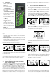
3.5 Further Device Functions
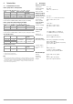
Phase Detection
If the symbol appears in the lower right-hand corner of the
display (see figures 2.4 and 2.5), and if a phase is contacted with
the fixed test probe, the symbol is changed to .
The other test probe may not be connected anywhere or make
any contact at all!
Note
As usual, the test instrument must be gripped in the
hand!
In order to obtain a correct display, the fixed test probe
must remain connected to the phase for at least 2 sec-
onds.
Phase voltage to ground must be 190 V / 48 to 52 Hz,
because the display will otherwise be incorrect.
Measuring Point Illumination with White LED
The LED can be switched on and off by briefly pressing the START
key.
No voltage may be applied to the test probes.
Selecting Brief or Detailed Representation, Information on Firm-
ware Version
➭ Press the START key to switch the instrument on while pressing
and holding the ~/RCD key. The version number appears at
the display, for example V 1.0.0, along with corresponding
symbols for the desired representation.
➭ Select the representation mode with the DISP ▲ (brief) or DISP
▼ (detailed) key. After selection, the instrument is switched
back to normal operation.
3.6 Device Reset Function
If the test instrument does not function as described in these
instructions, we recommend a device reset. The test instrument
must be switched off and neither of the test probes may be con-
nected to a DUT. If device functions are still incorrect after switch-
ing the instrument back on again, remove the batteries as
described in section 6.1 on page 10, wait at least 10 seconds
and then reinsert the batteries (or replace them with new ones).
If the test instrument still does not function as described, remove
the batteries and contact our service department.
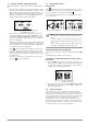
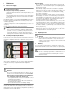
Figure 3.23: Display of Smallest Short-Circuit Current
for Shutting Down a B16 Breaker
Figure 3.24: Phase Display (brief) Figure 3.25: Phase Display (detailed)
Figure 3.26: Selecting Brief or Detailed Rep-
resentation, Firmware Version