
User manual

6 GMC-I Messtechnik GmbH
3.3.2 Displaying Further Measured/Calculated Values
Stated briefly: The following are displayed, one after the other, by
pressing the DISP
▲ and DISP ▼ keys:
– Short-circuit current
– 1.5 times measured impedance
– Impedance corrected by a value equal to measuring error
– Measured impedance
In detail: Impedance corrected by a value equal to measuring error
is displayed by pressing the DISP
▲ key, and only the measured
value without correction is displayed by pressing the DISP
▼ key.
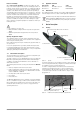
3.3.3 Measurement in Electrical Circuits with RCD
Testing Without Tripping the RCCB
Select the “RCD” function if loop impedance needs to be mea-
sured via an RCCB, without causing it to trip.
➭ After switching the instrument on, connect it between L and N
in order to measure line impedance.
➭ After the voltage value has settled in, briefly press the ~/RCD
key, which starts measurement of line impedance without trip-
ping the RCD. This is important if loop impedance needs to be
measured via an RCCB.
➭ Assure good contact between the test probes and the device
under test while measurement is being performed!
Attention!
!
This function is only possible for RCCB‘s (RCD‘s) with
IΔN ≥ 100 mA. It cannot be guaranteed for 10 mA and
30 mA, see also Safety Precautions in chapter 1.3.
The results appear at the display, and the “~” symbol is replaced
with the “RCD” symbol at the same time.
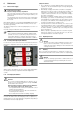
Testing With Tripping of the RCCB
➭ Connect the test probe from N to PE (see example in figure
3.12).
➭ Start the measurement by pressing the START key. Assure
good contact between the test probes and the device under
test while measurement is being performed!
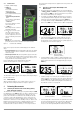
After the measurement has been completed, the results are dis-
played as follows:
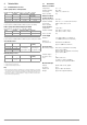
Key:
Z Measured impedance ()
Z x 1.5 Multiplier for measured impedance Z ()
I
K Short-circuit current calculated as: IK = 230 / (Z x 1.5) (A)
➭ Several seconds after the measurement cables have been re-
moved from the device under test, the test instrument is
switched back to the “~” function. In order to perform further
loop impedance measurements, the entire procedure in ac-
cordance with section 3.3.3 on page 6 must be repeated.
➭ In order to display additional measured/calculated values, pro-
ceed as described in section 3.3.2 on page 6, “Displaying Fur-
ther Measured/Calculated Values”.
Note: Contact PE with the mobile test probe. Press the START key. If
no voltage is present, loop impedance measurement is not
started. Assure that the test probes make good contact with L
and PE.
Make certain that:
– L and PE are contacted
– PE is securely connected
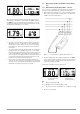
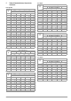
Figure 3.15: Short-Circuit Current Figure 3.16: 1.5 Times Impedance
Figure 3.17: Impedance + Measuring
Error
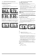
Figure 3.18: Measured Impedance
Figure 3.19: Measured Impedance +
Measuring Error
Figure 3.20: Measured Impedance
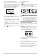
Figure 3.21: Impedance Downstream
from an RCCB (brief)
Figure 3.22: Impedance Downstream
from an RCCB (detailed)