
User manual

GMC-I Messtechnik GmbH 5
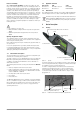
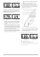
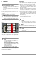
When the maximum permissible internal temperature has been
exceeded, the “T” symbol is replaced with the “STOP” symbol. If
the START key is pressed and held for approximately 1 second,
overheating is displayed and any further measurements are dis-
abled. Allow the instrument to cool down!
➭ Securely contact the device under test with the test probes.
Afterwards, check to see whether or not the displayed line
voltage value is stable. Always assure good contact during
measurement in order to prevent distortion of the measure-
ment results.
• The test instrument evaluates deviation while measurement is
being performed. If considerable interference occurs within
the measured system during measurement which would lead
to inaccurate impedance measurement results, impedance
does not appear at the display and the instrument is switched
to voltage measurement after measurement has been com-
pleted. The measurement must be repeated!
• If line voltage is unstable while measurement is being per-
formed, or if other electrical circuits parallel to the measured
circuit are in use, measurement results may be distorted and
permissible measuring error may be exceeded.
3.3 Measurement of Fault Loop Impedance and Line Imped-
ance
3.3.1 Measurement in Circuits without RCD –
~ Function
The “~” function is suitable for measuring fault loop impedance in
electrical circuits without RCCBs, as well as line impedance.
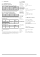
➭ After switching the instrument on, connect it between L and
PE in order to measure fault loop impedance, and between L
and N to measure line impedance.
➭ After the voltage value has settled in, briefly press the START
key in order to trigger measurement. Assure good contact be-
tween the test probes and the device under test while mea-
surement is being performed!
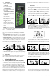
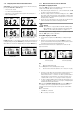
Results after completion of the measurement:
Key:
Z Measured impedance ()
Z x 1.5 Multiplier for measured impedance Z ()
IK Short-circuit current calculated as: I
SC
= 230 / (Z x 1.5) (A)
➭ Remove the instrument.
Figure 3.8: High Temperature Display
(brief representation)
Figure 3.9: High Temperature Display
(detailed representation)
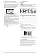
Figure 3.10: Overheating Display – STOP
Symbol
Figure 3.11: Overheating Display After
Pressing the Start Key
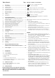
Figure 3.12: Connection Example: Loop Impedance Measurement, L2–PE
Figure 3.13: Sample Results for Imped-
ance Measurement (brief
representation)
Figure 3.14: Sample Results for Imped-
ance Measurement
(detailed representation)