
User manual

4 GMC-I Messtechnik GmbH
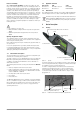
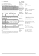
2.2 Control Panel
1 Graphic OLED Display
2 START key:
– Switch on:
Press and hold until the
display lights up.
– Start measurement:
Press and hold until measure-
ment starts.
– Measurement point illumina-
tion:
Press briefly to switch illumi-
nation on and off.
– Switch off:
Press twice briefly to switch
the instrument off.
3 ~ / RCD key
Measuring function selection:
with/without RCCB
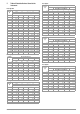
4The T
A
key is used to select
the value from the table of
protective devices, which is
used to adjust disconnection
time for evaluating measured
values.
5 DISP ▲ and
DISP
▼ keys for selecting the
protective device for the evaluation of measured values
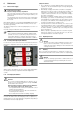
Figure 2.3: Control Panel and OLED Display
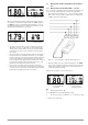
Data can be represented at the OLED display in two different
ways:
• Brief representation: Measured quantities appear at the display
with large numbers, but no evaluation of the measurement
data is included.
• Detailed representation: Measured quantities appear at the dis-
play along with information from the protective devices data-
base, as well as the symbol for “corresponds / does not cor-
respond with the measured impedance”.
Phase and battery level are displayed in both modes.
Refer to the description in section 3.5 on page 7
The information which appears at the display varies depending on
the selected function.
2.3 Initial Start-Up
After inserting the batteries in accordance with section 6.1 on
page 10, the measuring instrument is ready for operation.
3 Performing Measurements
3.1 Switching the Instrument On and Off, Energy-Saving
Mode, Automatic Shutdown
The instrument is switched on by pressing and holding the START
key. Briefly press the START key twice in order to switch the instru-
ment off, during which no voltage may be applied to the test
probes! The instrument is switched to the standby mode after
several seconds (reduced brightness), if none of the keys has
been pressed and no voltage is applied to the test probes. The
instrument is switched out of the standby mode (i.e. back to full
brightness) by pressing any key or applying voltage to the test
probes. The instrument is shutdown automatically if it has
remained inactive for about 1 minute, i.e. if no keys have been
pressed and no voltage has been applied to the test probes dur-
ing this time.
3.2 Instructions and Principles with Validity for All
Measurements
• The desired functions and parameters are selected with the
~/RCD, T
A
, DISP ▲ and DISP ▼ keys. Measurement is triggered
by pressing the START key. All selected functions or parame-
ters remain valid until they are changed.
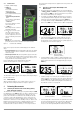
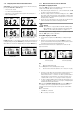
• If a voltage of < 24 V or > 260 V is applied to the test probes,
corresponding information appears at the display and mea-
surement cannot be triggered by pressing the START key.
• If a voltage within a range of 24 V to 190 V is applied to the test
probes, the START key is disabled and “< 190 V” is displayed.
• If the test instrument displays voltage applied to the test
probes after the START key has been pressed, although no
measurement ensues and the blown fuse symbol appears at
the display, the fuse must be replaced.
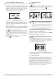
• If voltage within a range of 190 V to 260 V is applied to the
test probes, the momentary measured value appears at the
display and measurement can be triggered by pressing the
START key.
• If battery voltage is too low (only the red field is lit up in the
battery symbol), measurement cannot be started. After press-
ing the START key, the depleted battery symbol appears for
about 1 second (see figure below). Replace the batteries as
described in section 6.1 on page 10.
• If several impedance measurements are performed one after
the other, internal warming of the instrument is displayed by
means of the red indicator – “T” symbol. As temperature
increases, the field is gradually filled in and becomes wider.
Figure 2.4: Example of Brief
Representation
Figure 2.5: Example of Detailed
Representation
3
1
2
4
5
5
Figure 3.1:Voltage < 24 V
(brief representation)
Figure 3.2: Voltage < 24 V
(detailed representation)
Figure 3.3: Blown Fuse Example
(detailed representation)
Figure 3.4: Voltage Measurement
(brief representation)
Figure 3.5: Voltage Measurement
(detailed representation)
Figure 3.6: Low Battery Voltage
(detailed representation)
Figure 3.7: Display After Pressing START
(detailed representation)