Operating Instructions METRALINE ZCHECK Loop Resistance Measuring Instrument 3-349-697-03 2/4.
Table of Contents Page 1 Introduction ...................................................................... 2 1.1 1.2 1.3 1.4 1.5 Scope of Delivery ...........................................................................2 Optional accessories ......................................................................2 Safety Precautions .........................................................................2 General Device Description .............................................................
Exclusion of Liability 1.5 When testing systems with RCCBs, the latter may switch off. This may occur even though the test does not normally provide for it. Leakage currents may be present which, in combination with the test current of the test instrument, exceed the shutdown threshold value of the RCCB. PCs which are operated in proximity to such RCCB systems may switch off as a consequence. This may result in inadvertent loss of data.
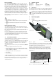
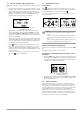
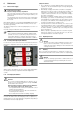
2.2 Control Panel 1 Graphic OLED Display 2 START key: – Switch on: Press and hold until the display lights up. – Start measurement: 1 Press and hold until measurement starts. – Measurement point illumination: 2 Press briefly to switch illumination on and off. 3 – Switch off: Press twice briefly to switch the instrument off.
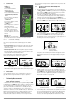
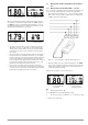
3.3 Measurement of Fault Loop Impedance and Line Impedance 3.3.1 Measurement in Circuits without RCD – ~ Function Figure 3.8: High Temperature Display (brief representation) Figure 3.9: High Temperature Display (detailed representation) The “~” function is suitable for measuring fault loop impedance in electrical circuits without RCCBs, as well as line impedance.
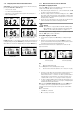
3.3.2 Displaying Further Measured/Calculated Values 3.3.3 Measurement in Electrical Circuits with RCD Stated briefly: The following are displayed, one after the other, by pressing the DISP ▲ and DISP ▼ keys: – Short-circuit current – 1.5 times measured impedance – Impedance corrected by a value equal to measuring error – Measured impedance Testing Without Tripping the RCCB Figure 3.15: Short-Circuit Current Figure 3.16: 1.
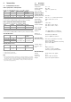
3.4 Automatic Evaluation of Measured Impedance Automatic evaluation is only possible with the detailed representation. • Protective device parameters are stored to memory or to the database. Type, nominal current In and disconnection time ta appear at the top of the display (see example in figure 2.5). After pressing the TA key for the first time, disconnection time ta and the smallest short-circuit current IFmin required for shutdown appear at the bottom of the display. Figure 3.
4 Technical Data 4.1 Individual Device Functions 4.2 Reference Conditions Fault Loop Impedance / Line Impedance Nominal Range per EN 61557-3: 0.27 to 200 Range Resolution Intrinsic Uncertainty Measuring Uncertainty 0.00 to 4.99 0.01 (3% rdg. + 5 D) (4% rdg. + 7 D) 5.0 to 49.9 0.1 (3% rdg. + 3 D) (4% rdg. + 4 D) 50 to 200 1 3% rdg. 4% rdg.
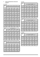
5 Table of Protective Devices Stored to the Instrument Fuse Type C Nominal Current (A) Fuse Type NV Nominal Current (A) Disconnecting Time [s] 35m 0.1 02 0.4 5 Min. Short-Circuit Current (A) Disconnecting Time [s] 35m 0.1 02 0.4 05 5 5 5 5 2.7 1 10 10 10 10 5.4 1.6 16 16 16 16 8.6 5 Min. Short-Circuit Current (A) 32.5 22.3 18.7 15.9 9.1 2 20 20 20 20 10.8 4 65.6 46.4 38.8 31.9 18.7 4 40 40 40 40 21.6 6 102.8 70 56.5 46.4 26.
6 Maintenance 6.1 Device Power Supply Caution: Dangerous Voltage! Dangerous voltage in battery compartment! Disconnect the test probes from the device under test and switch the instrument off before removing the battery compartment lid. The instrument may not be placed into service if the battery compartment lid has not been inserted and secured with the screws.
6.3 7 Recalibration The measuring tasks performed with your instrument, and the stressing it’s subjected to, influence aging of its components and may result in deviation from the specified levels of accuracy. If required please contact: In the case of strict measuring accuracy requirements, as well as in the event of use at construction sites with frequent stress due to transport and considerable temperature fluctuation, we recommend a relatively short calibration interval of once per year.