
User manual

16 GMC-I Messtechnik GmbH
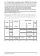
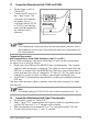
8 Resistance Measurement
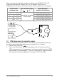
➭ Set the rotary switch to the
position. Overload is indicated
if no device under test has been
connected: “0.L M”.
➭ Before connecting the device under
test, make sure that it is voltage-
free. Interference voltages distort
measurement results! Perform a
voltage test first if required.
➭ Connect the device under test as
shown in the diagram.
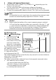
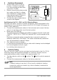
Zero Balancing in the 30 , 300 and 3 kMeasuring Ranges
Resistance at cables, as well as contact resistances, can be eliminated for the
measurement of low-resistance values in the 30 , 300 and 3 k ranges by
means of zero balancing:
➭ Connect the measurement cables to the instrument and connect the free
ends to one another (short circuit the test probes).
➭ Briefly press the FUNC key.
The instrument acknowledges zero balancing with an acoustic signal, and
“00
.00 ”, “ 000.00 ” or “0.0000 k”and the ZERO symbol appear at the
LCD.
Resistance measured at the moment the key is pressed is used as a
reference value (max. 2000 digits). This value is automatically subtracted
from all subsequently measured values.
➭ Zero balancing can be cleared:
– by pressing and holding the FUNC key, after which clearing is acknowledged
by a twice repeated acoustic signal,
– by switching the instrument off.
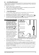
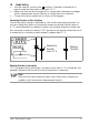
9 Continuity Testing
With the “acoustic signal” function activated, and exclusively in the 0 to 310
measuring range, the instrument generates a continuous acoustic tone for
measured resistance within a range of 0 to approximately 2 .
➭ Turn the selector switch to the position. The and symbols appear at
the LCD.
➭ Connect the measurement cables to the device under test.
Note!
Continuity testing is very fast (< 50 ms) and is suitable for locating
connections with poor contact (e.g. due to vibration) in automotive
service applications.
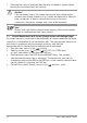
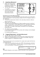
R
x
Voltage Drop