
User manual

GMC-I Messtechnik GmbH 13
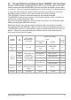
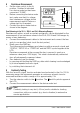
6.1 Low-Voltage Measurement
The instrument is equipped with a special 30 mV measuring range for measuring
voltage drop at fuses which is distinguished by high resolution (10 V) with a low
input resistance of 50 k.
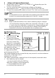
➭ Set the rotary switch to “Temp RTD”.
➭ Select “V DC” measurement with probe by repeatedly pressing the FUNC
key until “mV DC” appears at the display.
➭ Connect
the probe to the “” and “V” sockets.
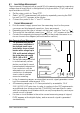
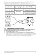
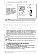
7 Current Measurement
➭ First disconnect supply power from the measuring circuit or the power
consumer and discharge all capacitors, if any are present.
➭ Depending upon the type of current, set the rotary switch to “A ” or “A ”.
➭
The symbol for the selected current type, (DC) or ~ (AC), appears at the LCD.
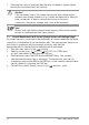
➭ Connect the measuring instrument securely to the power consumer in se-
ries as shown in the diagram (without transition resistor).
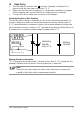
Notes Concerning Current Measurement:
• The instrument may only be
used in power installations if
the electrical circuit is pro-
tected with a fuse or a circuit
breaker with a rating of up to
20 A, and if nominal voltage at
the system does not exceed
240 V~ (AC) or 50 V (DC).
• Set up the measuring circuit
in a mechanically secure
fashion such that it cannot
be inadvertently interrupted.
Use conductors with an
adequate cross section and
connectors of adequate
size in order to prevent
excessive warming.
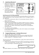
• In the A measuring ranges, an intermittent acoustic signal generates a warn-
ing if the measured value exceeds 10 A.
• All measuring ranges up to 10 A are protected by a resetable, 15 A/
240 V AC/50 V DC auto-fuse. In order to conform to the CAT requirements,
an additional slow-blowing fuse link (T16A/500V) has been fitted in series
with the miniature circuit breaker which can only be replaced by service per-
sonnel once it is tripped.
• If a fuse or circuit breaker in the active current measuring range is tripped,
FUSE appears at the digital display, and an acoustic signal is generated
simultaneously.
– (+)
~
+ (–)
~