
User manual


12 GMC-I Messtechnik GmbH
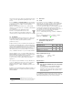
11 Capacitance Measurement
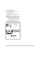
➭ Make sure that the device under test is voltage-free.
Interference voltages distort measurement results!
➭ Turn the rotary switch to the “F” position.
➭ Connect the (discharged!) device under test to the and V
jacks with the measurement cables
Note!
The “–“ pole of polarized capacitors must be
connected to the „“ jack.
Resistors and semiconductor paths connected in
parallel to the capacitor distort measurement results!
12 Frequency Measurement – Duty Cycle Measurement
➭ Turn the rotary switch to the Hz position.
➭ Apply the measured quantity as described under voltage
measurement.
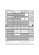
➭ Smallest measurable frequencies and maximum
allowable voltages are listed in chapter 14 “Characteristic
Values”.
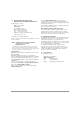
12.1 Duty Cycle Measurement
The pulse-period ratio can be ascertained for square-wave
signals with the duty cycle measurement.
➭ Turn the rotary swith to Hz position
➭ Briefly press the multifunction FUNC key twice. The
instrument is switched to duty cycle measurement. The
duty cycle, i.e. the pulse duration of a signal as a
percentage, is displayed at the LCD.
Note!
The applied frequency must remain constant during
duty cycle measurement.
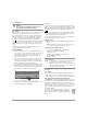
12.2 RPM Measurement
RPM is measured by acquiring pulses. The number of
measurable pulses per revolution varies depending upon the
type of engine.
➭ Set the rotary switch to Hz.
➭ Press the multifunction key FUNC twice until unit of
measure RPM appears.
The measured value then appears, for
example
“244.3 RPM”.
+
–
F
00.00
nF
F: 40 nF 400 μF
Messbereich:
Duty Cycle (%) = ——————— • 100
Pulse Duration
Period