
Datasheet


GMC-I Messtechnik GmbH 3
METRAHITWORLD
International TRMS Multimeter
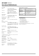
Influencing Quantities and Influence Error
1)
For temperature: specified error valid starting with temperature changes as of 10 K.
For frequency: specified error valid starting with display values as of 300 digits.
2)
With zero balancing
3)
After the symbol appears at the display
Crestfaktor CF
Test signal: Rectangle 55 Hz, no DC component
The admissible crest factor CF of the alternating quantity to be
measured depends on the display value.
Crest factor 4 at the end of range, it is increased accordingly
when the range is reduced. However, due to input protection,
voltage is limited to 1000 V, therefore the admissible crest factor
in the 600 V ranges is half as high.
Power limiting: voltage x frequency max. 3 x 10
6
V x Hz.
Response Time (after manual range selection)
Display
LCD panel (65 mm x 30 mm) with analog and digital display
including unit of measure, type of current and various special
functions
Analog
:
Display LCD scale with pointer
Scale length 55 mm in all ranges
Scaling 0 ... ± 60 with 61scale divisions in all
ranges
Polarity display With automatic switching
Overflow display Triangle
Measuring rate 30 measurements per second
Digital:
Display / char. height 7-segment characters / 15 mm
Number of places 3
6
/
7
-place , 6000 steps
Overflow display
„0. L“ appears
Polarity display “–” sign is displayed if plus pole is
connected to ⊥
Measuring rate 3 measurements per second
Electromagnetic Compatibility (EMC)
Interference emission EN 61326-1: 2006 class B
Interference immunity EN 61326-1: 2006
EN 61326-2-1:2006
Influencing
Quantity
Sphere of Influence
Measured Quantity /
Measuring Range
Influence Error
1)
±(... % rdg. + ... digits)
Temperature
0 °C ... +21 °C
and
+25 °C ... +40 °C
600 mV 1.0 + 3
6 ... 600 V 0.15 + 1
1000 V 0.2 + 1
V0.4+2
0 Ω
2)
0.15 + 2
600 Ω
2)
0.25 + 2
6kΩ ... 6 MΩ 0.15 + 1
40 MΩ 1.0 + 1
mADC, ADC 0.5 + 1
mAAC, AAC 0.75 + 1
– 50 ... + 200 °C 0.5 K + 2
+ 200 ... + 400 °C 0.5 + 2
Measured
Quantity
Frequency
> 30 Hz ... 45 Hz A 2.0 + 10
> 65 Hz ... 1 kHz
60 / 600 mA / 6 A 1.5 + 10
10 A 2 + 10
> 30 Hz ... 45 Hz
600 mV 3 + 10
6 / 60 /600 V 2.5 + 10
1000 V 3.5 + 20
> 65 Hz ... 500 Hz 600 mV 35 + 20
> 65 Hz ... 800 Hz
6 / 60 V 2.5 + 10
600 V 3 + 20
1000 V 3.5 + 20
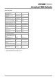
Influen-
cing
Quantity
Sphere of Influence
Measured Quantity /
Measuring Range
Influence Error
Battery
Voltage
3)
... < 2.9 V
> 3.1 V ... 3.6 V
V ± 2 Digits
V ± 4 Digits
A ± 4 Digits
A ± 6 Digits
60 Ω / 600 Ω / °C ± 4 Digits
6kΩ ... 40 MΩ±3 Digits
Relative
Humidity
75%
3 days
Instrument off
V
A
Ω
°C
1 x intrinsic uncertainty
HOLD — ± 1 Digits
MIN / MAX — V , A ± 2 Digits
Influencing
Quantity
Sphere of Influence
Measuring
Ranges
Damping
Common Mode
Interference
Voltage
Interference quantity max. 600 V V > 120 dB
Interference quantity max. 600 V
50 Hz, 60 Hz sine
3 V , 30 V > 80 dB
300 V > 70 dB
600 V > 60 dB
Series Mode
Interference
Voltage
Interference quantity: V ,
respective nominal value
of the measuring range,
max. 600 V , 50 Hz, 60 Hz
sine
V > 50 dB
Interference quantity max. 600 V V > 110 dB
Influencing
Quantity
Sphere of Influence
Measured Quantity /
Measuring Range
Influence Error
Crest factor CF
1.5 < CF ≤ 2
6 V, 60 V, 600 V,
1000 V
±1% rdg.
2 < CF ≤ 4 ±5% rdg.
Measured Quantity /
Measuring Range
Response Time
Measured Quantity
Step Function
Analog Display Digital Display
V , V ,
A , A
0.7 s 1.5 s
from 0 to 80%
of the upper range limit
600 Ω ... 6 MΩ 1.5 s 2 s
from ∞ to 50%
of the upper range limit
40 MΩ 4 s 5 s
— 1.5 s
—< 50 ms
°C—max. 3 s
from 0 to 50%
of the upper range limit
F—max. 5