
User manual
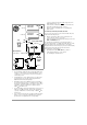
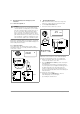
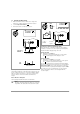
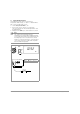
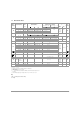
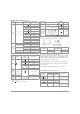
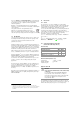
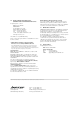
Table Of Contents
- 1 Safety Features and Precautions
- 2 Initial Start-Up
- 3 Selecting Measuring Functions and Measuring Ranges
- 4 LCD
- 5 Measured Value Memory “HOLD”
- 6 Saving Minimum or Maximum Values “MIN/MAX” Hold
- 7 Voltage Measurement
- 8 Current Measurement
- 9 Resistance Measurement
- 10 Continuity and Diode Testing
- 11 Temperature Measurement
- 12 Characteristic Values
- 13 Maintenance
- 14 Recalibration
- 15 Accessories
- 16 Repair and Replacement Parts Service, Calibration Center* and Rental Instrument Service
- 17 Manufacturer‘s Guarantee
- 18 Product Support
14 GMC-I Messtechnik GmbH
Influencing Quantities and Influence Error
1)
For temperature: specified error valid starting with temperature changes as of 10 K.
For frequency: specified error valid starting with display values as of 300 digits.
2) With zero balancing
3) After the symbol appears at the display
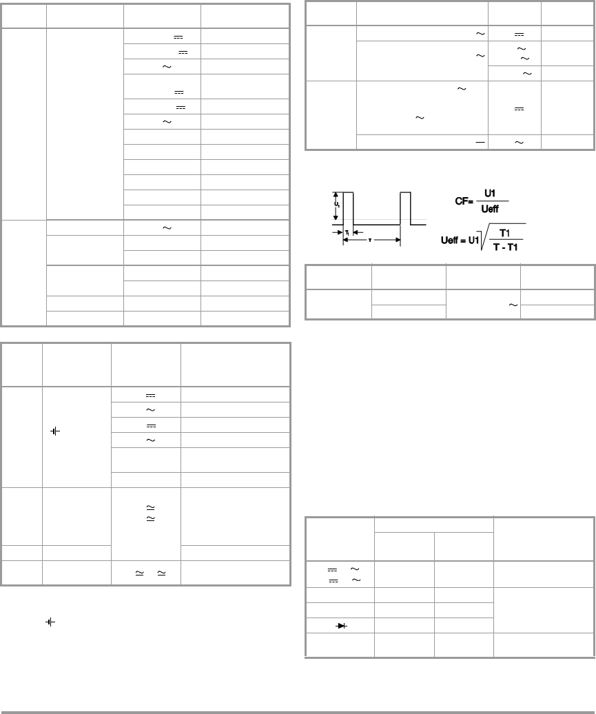
Crestfaktor CF
Test signal: Rectangle 55 Hz, no DC component
The admissible crest factor CF of the alternating quantity to
be measured depends on the display value.
Crest factor 4 at the end of range, it is increased accordingly
when the range is reduced. However, due to input protection,
voltage is limited to 1000 V, therefore the admisible crest fac-
tor in the 600 V ranges is half as high.
When the waveform is unknown, measurement is to be per-
formed with manual range selection in the case of higher fre-
quency signals.
Power limiting: voltage x frequency max. 3 x 10
6
V x Hz.
Response Time (after manual range selection)
Influencing
Quantity
Sphere of Influence
Measured Quantity /
Measuring Range
Influence Error
1)
(... % rdg. + ... digits)
Tempera -
ture
0 C ... +21 C
and
+25 C... +40 C
600 mV 1.0 + 3
6 ... 600 V 0.15 + 1
V0.4+2
60 mA ...
600 mA
0.5 + 1
6A/10A 0.5+1
A0.75+1
0
2)
0.15 + 2
600 0.25 + 2
6k ... 6 M 0.15 + 1
40 M 1.0 + 1
– 50 ... + 200 C1 K + 2
+ 200 ... + 400 C1 + 2
Measured
Quantity
Frequency
> 30 Hz ... 45 Hz A 2.0 + 10
>65Hz...1kHz
60 / 600 mA / 6 A 1.5 + 10
10 A 2 + 10
> 30 Hz ... 45 Hz
600 mV 3 + 10
6 / 60 /600 V 2.5 + 10
> 65 Hz . ... 500 Hz 600 mV 3.5 + 20
> 65 Hz ... 800 Hz 6 / 60 V 2.5 + 10
Influen-
cing
Quantity
Sphere of
Influence
Measured
Quantity /
Measuring
Range
Influence Error
Battery
Voltage
3)
... < 2.9 V
> 3.1 V ... 3.6 V
V 2 Digits
V 4 Digits
A 4 Digits
A 6 Digits
60 / 600 /
C
4 Digits
6k ... 40 M3 Digits
Relative
Humidity
75%
3 days
Instrument off
V
A
C
1 x intrinsic error
HOLD — 1 Digits
MIN /
MAX
—V, A 2 Digits
Influencing
Quantity
Sphere of Influence
Measuring
Range
Damping
Common
Mode
Interference
Voltage
Interference quantity max. 600 V V > 120 dB
Interference quantity max. 600 V
50 Hz, 60 Hz sine
6V ,
60 V
>80dB
600 V > 70 dB
Series Mode
Interference
Voltage
Interference quantity: V ,
respective nominal value
of the measuring range,
max. 600 V , 50 Hz, 60 Hz
sine
V > 50 dB
Interference quantity max. 600 V V > 110 dB
Influencing
Quantity
Sphere of Influence
Measured Quantity /
Measuring Range
Influence Error
Crest factor CF
1.5 < CF 2
6 V, 60 V, 600 V
1% rdg.
2 < CF 4 5% rdg.
Measured
Quantity /
Measuring
Range
Response Time
Measured Quantity
Step Function
Analog Display Digital Display
V, V,
A, A
0.7 s 1.5 s
from 0 to 80%
of the upper range limit
600 ...6M 1.5 s 2 s
from to 50%
of the upper range limit
40 M 4s 5s
—1.5s
C — max. 1 ... 3 s
from 0 to 50%
of the upper range limit