
Data Sheet

GMC-I Messtechnik GmbH 5
METRAHITIM XTRA & METRAHITIM E-DRIVE
Isolation Tester, Milliohmmeter,
TRMS Multimeter, Short-Circuited Coil Tester
Insulation Measurement
1
TRMS interference voltage measurement (V
AC+DC
) with 1 M input resistance,
frequency response width: > 65 ... 500 Hz, accuracy: 3% + 30 digits
Short-Circuited Coil Test (only with optional COIL adapter)
1
TRMS interference voltage measurement (V
AC+DC
) with 1 M input resistance,
frequency response width: > 65 ... 500 Hz, accuracy: 3% + 30 digits
2)
The time value may vary for differnt COIL adapters by up to 10 %. This has no influence whatsoever
if you perform the measurements with the same COIL adapter and compare them with each other.
Inductance measuring ranges of optional COIL adapters:
• COIL adapter XTRA (Z270M): 10 µH up to 5 H
• COIL adapter 50mH (Z270F): 10 µH up to 50 mH
Internal Clock
Time format DD.MM.YYYY hh:mm:ss
Resolution 0.1 s (measured values time stamp)
Accuracy 1 minute per month
Temperature
influence 50 ppm/K
Reference Conditions
Ambient temperature +23 C 2K
Relative humidity 40% 75%
Measured quantity
frequency 45 Hz 65 Hz
Measured quantity waveform
Sinusoidal
Supply voltage 4.0 V 0.1 V
Influencing Quantities and Influence Error
1
With zero balancing
Frequency Influence for V
AC
V
AC+DC
Voltage Ranges
1
For sinusoidal input signals > 10% to 100% of the range (mV range: as of 30% of
range, at 1% to 10% of the range: f < 50 kHz, intrinsic error increased by 0.2% of
the upper range limit.
2
Overload capacity of the voltage measurement input:
power limiting: frequency x voltage max. 6 x 10
6
V x Hz at > 100 V
Frequency Influence for I
AC
/ I
AC+DC
Current Measuring Ranges
1
For sinusoidal input signals > 10% to 100% of the range.
1
Except for sinusoidal waveform
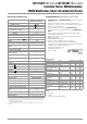
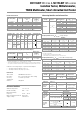
Measuring Range Resolution
Nominal Voltage
U
ISO
Intrinsic Uncer-
tainty at Reference
Conditions
(% rdg. + d)
3 ... 1000 V
1
Ri = 1M
3 + 3
300 k 0.1 k
50/100/250/500 V
2 + 10
3 M 1k
50/100/250/500/1000 V
2 + 10
30 M 10 k
50/100/250/500/1000 V
2 + 10
300 M 100 k
50/100/250/500/1000 V
5 + 10
3000 M 1M
250/500/1000 V
5 + 10
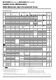
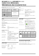
Measuring
Function
Nom.
Voltage
U
N
Open-
Circuit
Voltage
U
o
Max.
Nom.
Cur-
rent I
N
Short-
Circuit
Cur-
rent I
k
Acoustic
Signal
for
Overload Capacity
Value Time
U
int.
/
M
@
U
ISO
— —— —
U > 1000 V
1000 V Cont.
M
@
U
ISO
50
100
1.2x
U
Iso
1.0 mA
<1.4
mA
U > 1000
V
1000 V 10 s
250
500 V
1000 V
1.12x
U
Iso
Measuring Range Resolution
Nominal Voltage
U
ISO
Intrinsic Uncer-
tainty at Reference
Conditions
(% rdg. + d)
0.3 ... 1000 V
1
Ri = 1M
3 + 30 > 100 digits
10.0 ... 30.9 μs 0.1 [μs]
1000 V
10 + 5 digits
31 ... 250 μs 1 [μs]
Influencing
Quantity
Sphere of
Influence
Measured Quantity /
Measuring Range
1
Influence Error
(...% rdg. + ... d) / 10 K
Temperature
0 C ... +21 C
and
+25 C... +40 C
V 0.2 + 5
V 0.4 + 5
300 ... 3 M 0.5 + 5
30 M 1 + 5
mA/A 0.5 + 5
mA/A 0.8 + 5
30 nF ... 300 F2 + 5
Hz 0.2 + 5
C/F (Pt100/Pt1000) 0.5 + 5
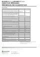
Deviation
1
Frequency Range
300 mV range
± (... % rdg. + ... d)
3 V, 30 V, 300 V range
2
± (... % rdg. + ... d)
1000 V range
2
± (... % rdg.)
15 Hz ... 45 Hz 2 + 30 2 + 30 2 + 30
> 65 Hz ... 1 kHz 0.5 + 30 0.5 + 30 1 + 30
> 1 kHz ... 10 kHz 2 + 30 1.5 + 30 10 + 30
> 10 kHz ... 20 kHz 3 + 30 1.5 + 30 —
> 20 kHz ... 50 kHz 3 + 30 5 + 30 —
> 50 kHz ... 100 kHz 10 + 30 10 + 30 —
Influence Error
1
Frequency Range
300 A to 300 mA
± (... % rdg. + ... digits)
1 A range
± (... % rdg. + ... digits)
15 Hz ... 45 Hz 2 + 30 2 + 30
> 65 Hz ... 1 kHz 1 + 30 1 + 30
> 1 kHz ... 2 kHz 1 + 30 1 + 30
> 2 kHz ... 5kHz 1 + 30 3 + 30
> 5 kHz ... 10 kHz 5 + 30 5 + 30
Influencing
Quantity
Sphere of
Influence
Measured Quantity /
Measuring Range
Influence Error
1
Crest Factor CF
1 … 3
V, A
1% rdg.
> 3 ... 5 3% rdg.
Influencing
Quantity
Sphere of
Influence
Measured Quantity Influence Error
Relative
Atmospheric
Humidity
75%
3 days
instrument off
V, A, , F, Hz, C 1 x intrinsic uncertainty
Battery Voltage ditto
Included in intrinsic
uncertainty
Influencing
Quantity
Sphere of Influence
Measured Qty. /
Measuring Range
Damping
Common Mode
Interference
Voltage
Interference quantity max. 1000 V V > 90 dB
Interference quantity max. 1000 V
50 Hz ... 60 Hz, sinusoidal
3 V > 90 dB
30, 300 V > 150 dB
1000 V > 150 dB
Series Mode
Interference
Voltage
Interference quantity: V ,
respective nominal value of the
measuring range,
max. 1000 V , 50 Hz ... 60 Hz sinu-
soidal
V> 50dB
Interference quantity max. 1000 V V > 50 dB