
User Manual


34
8. Maintenance
No maintenance is required.
9. Releasing the transducer
Release the transducer from a top-hat rail as shown in
Fig. 16.
0.25c
0.25c
0.25c
.15+0.03c
1.0
0.25
P
0W
500W
0.0mA
20.0mA
15+ 16–A
400kV/400V 1000/1.0A 50Hz 3N~
U1N
215V
240V
0.0mA
20.0mA
17+ 18–B
19+ 20–C 21+ 22–D
I1
0.000A 0.0mA
F
49.5Hz 0.0mA
20.0mA
23+ 24–G 25+ 26–H
P
5000 / kWh
I1<
U1N>
F>
0.500A 20.0mA 50.5Hz
0.225A
233V
50.0Hz
ON
Ydel=0s
OR
R
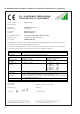
Fig. 14. Example of a type label with the present 20 mA output
and an accuracy class of 0.25 c.
0.45c
0.25c
0.25c
.15+0.03c
1.0
0.25
P
0W
500W
0.0mA
10.0mA
15+ 16–A
400kV/400V 1000/1.0A 50Hz 3N~
U1N
215V
240V
0.0mA
20.0mA
17+ 18–B
19+ 20–C 21+ 22–D
I1
0.000A 0.0mA
F
49.5Hz 0.0mA
20.0mA
23+ 24–G 25+ 26–H
P
5000 / kWh
I1<
U1N>
F>
0.500A 20.0mA 50.5Hz
0.225A
233V
50.0Hz
ON
Ydel=0s
OR
R
Fig. 15. Example of a type label with the new output of 10 mA
and an accuracy class of 0.45 c.
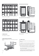
10. Dimensional drawings
1 2 3 4 5 6 7 8 9
11 13 14
15 16 17 18 19 20 21 22 23 24 25 26
150
123.487.5
165
6.5
Ø 4.5
12
19
181
Fig. 18. SINEAX DME in housing T24 screw hole mounting
brackets pulled out.
Fig. 17. SINEAX DME in housing T24 clipped onto a top-hat rail
(35 ×15 mm or 35×7.5 mm, acc. to EN 50 022).
1 2 3 4 5 6 7 8 9
11 13 14
15 16 17 18 19 20 21 22 23 24 25 26
150
157
124
87.5
1
2
3
4
5
6
7
8
9
11
13
14
Fig. 16
11. Safety notes
● Before you start the device check for which power supply
it is built.
● Verify that the connection leads are in good condition and
that they are electrically dead while wiring the device.
● When it must be assumed that safe operation is no lon-
ger possible, take the device out of service (eventually
disconnect the power supply and the input voltage!).
This can be assumed on principle when the device shows
obvious signs of damage.
The device must only be used again after troubleshooting,
repair and a final test of calibration and dielectric strength
in our factory or by one of our service facilities.