
User Manual


33
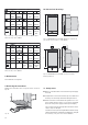
Fig. 11. Programmation of the output quantities.
• Definition of the digital outputs G and H, respectively E to
H, either to produce an output impulse (counter impulse)
for measuring Ah, Wh, Varh and VAh or to monitor a limit.
2 limit monitor outputs (G and H) permit up to 3 measure-
ments each to be logically interlocked.
Fig. 12. Assignment of limits to outputs E to H.
+
–
DME4
–
+
Fig. 13. Block circuit diagram for operation of the binary outputs.
Provision is also made for the following ancillary functions:
• The power system check
• Provision for displaying the measured variably on a PC
monitor
• The simulation of the outputs for test purposes
• Printing of nameplates
6.3 Operation of the binary outputs
The binary outputs are electrically isolated from all other
circuits via an optocoupler.
They therefore require an additional power supply to energise
the output circuits.
Outputs E, F, G and H in the case of SINEAX DME 424
and outputs
G and H in the case of SINEAX DME 442
are available (see Section “Electrical connections”).
External power supply: 8 … 40 V
Output current: ON 10 … 27 mA
OFF
≤ 2 mA
Fig. 10. Presentation of all programmation parameters in the
main menu.
7.1 Without hardware setting change
The PC software DME 4 (Order No. 146 557) and a pro-
gramming cable (Order No. 980 179) are needed in order to
reprogram the device. The reduced accuracy resulting from
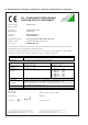
this change can be determined by printing a type label (see
Fig. 14 and 15).
7. Reconfiguring the analogue outputs
The alternative configurations for the analogue outputs can
be seen from Table 1.
Table 1:
Action Procedure
Change the current full-scale
value from, for example, 20 mA to
10 mA (a hardware setting always
has to be made when changing
from a lower to a higher value)
Reconfigure the softwa
-
re, but do not change the
hardware setting.
Accuracy is reduced
(see Section 7.1)
Unauthorized repair of alteration of the unit
invalidates the warranty!