
User Manual


30
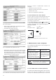
6.1 Technical data
Symbols
Symbols Meaning
X Measured variable
X0 Lower limit of the measured variable
X1 Break point of the measured variable
X2 Upper limit of the measured variable
Y Output variable
Y0 Lower limit of the output variable
Y1 Break point of the output variable
Y2 Upper limit of the output variable
U Input voltage
Ur Rated value of the input voltage
U 12 Phase-to-phase voltage
L1 – L2
U 23 Phase-to-phase voltage
L2 – L3
U 31 Phase-to-phase voltage
L3 – L1
U1N Phase-to-neutral voltage
L1 – N
U2N Phase-to-neutral voltage
L2 – N
U3N Phase-to-neutral voltage
L3 – N
UM Average value of the voltages
(U1N + U2N + U3N) / 3
I Input current
I1 AC current L1
I2 AC current L2
I3 AC current L3
Ir Rated value of the input current
IM Average value of the currents (I1 + I2 + I3)/3
IMS Average value of the currents and sign of the
active power (P)
IB RMS value of the current with wire setting
range (bimetal measuring function)
IBT Response time for IB
BS Slave pointer function for the measurement
of the RMS value IB
BST Response time for BS
ϕ
Phase-shift between current and voltage
F Frequency of the input variable
Fn Rated frequency
P Active power of the system
P = P1 + P2 + P3
P1 Active power phase 1
(phase-to-neutral L1 – N)
P2 Active power phase 2
(phase-to-neutral L2 – N)
P3 Active power phase 3
(phase-to-neutral L3 – N)
Q Reactive power of the system
Q = Q1 + Q2 + Q3
Symbols Meaning
Q1 Reactive power phase 1
(phase-to-neutral L1 – N)
Q2 Reactive power phase 2
(phase-to-neutral L2 – N)
Q3 Reactive power phase 3
(phase-to-neutral L3 – N)
S Apparent power of the system:
S1 Apparent power phase 1
(phase-to-neutral L1 – N)
S2 Apparent power phase 2
(phase-to-neutral L2 – N)
S3 Apparent power phase 3
(phase-to-neutral L3 – N)
Sr Rated value of the apparent power of the
system
PF Active power factor cosϕ = P/S
PF1 Active power factor phase 1 P1/S1
PF2 Active power factor phase 2 P2/S2
PF3 Active power factor phase 3 P3/S3
QF Reactive power factor sin ϕ = Q/S
QF1 Reactive power factor phase 1 Q1/S1
QF2 Reactive power factor phase 2 Q2/S2
QF3 Reactive power factor phase 3 Q3/S3
LF Power factor of the system
LF = sgnQ · (1 – | PF | )
LF1 Power factor phase 1
sgnQ1 · (1 – | PF1 | )
LF2 Power factor phase 2
sgnQ2 · (1 – | PF2 | )
LF3 Power factor phase 3
sgnQ3 · (1 – | PF3 | )
c Factor for the intrinsic error
R Output load
Rn Rated burden
H Power supply
Hn Rated value of the power supply
CT c.t. ratio
VT v.t. ratio
Input
Waveform: Sinusoidal
Nominal frequency: 50, 60 or 16 2/3 Hz
Consumption [VA]
(at external
power supply): Voltage circuit: U
2
/ 400 kΩ
Current circuit: ≤ I
2
· 0.01 Ω