
User Manual


29
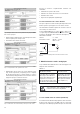
Fig. 7. Declaration to type label.
Measuring inputs
System /
application
Terminals
4-wire
3-phase
asymmetric
load
4-wire
3-phase
asymmetric
load,
Open Y
connection
3 single-pole insulated voltage transformers
in high-voltage system
Low-voltage system
2 single-pole insulated voltage transformers
in high voltage system
L1
L2
L3
k
l
K L
k
l
K L
k
l
K L
N
5
11
8
2
1
3
4 6
7
9
L1
L2
L3
N
5
11
8
2
1
3
4 6
7
9
L1
L2
L3
k
l
K L
k
l
K L
k
l
K L
N
xxx
uuu
X
XX
UU U
5
11
8
2
1
3
4 6
7
9
L1
L2
L3
k
l
K L
k
l
K L
k
l
K L
xx
uu
X
U
2
4
3
1
5
6
7 8
9
11
X
U
L
N
L1
L2
L3
k l
K L
k
l
K L
k
l
K L
N
8
2
1
3
4 6
7
9
11
0.25* c
0.25* c
0.25 c
0.25 c
0.25 c 0.25 c
P1
–115.47W
115.47W
–20mA
20mA
15+ 16–A
100V 2A 50Hz 3N~
P2
–115.47W
115.47W
–20mA
20mA
17+ 18–B
19+ 20–E 21+ 22–F
P>
311.77kW ON
Q>
34.64kvar ON
Ydel=min Ydel=min
23+ 24–G 25+ 26–H
P1>
115.47kW ON
I1>
2A ON
Ydel=min Ydel=min
6
7
8
9
10
SINEAX DME 424
Camille Bauer AG
CH - 5610 Wohlen
Switzerland
Ord: 123/45679/007/1
AC/DC 85-230 V
50/60 Hz 10 VA
IL1
IL2
IL3
1
4
7
3
6
9
UL
1
UL
2
UL
3
2
5
8
N 1
1
13
14
6. Commissioning
Prior to starting, check that the connection
data of the transducer agrees with the system
data (see type label).
The power supply to the transducer can then be switched
on and the signals applied to the measuring inputs.
Measuring input
Input voltage
Input current
Nominal frequency
System
Measuring output
Output signal
Power supply
6 Manufacturer
7 Works No.
8 Test and Conformity marks
9 Terminals
Input quantities and
power supply
10 Terminals
Output quantities