
User Manual


26
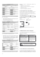
4.2 Fastening on a mounting surface
While pressing the latch (4) in the base of the device (Fig. 5,
left) pull out the isolating amplifier securing brackets (1). To
return the brackets to their original positions, the latch (5) in
the base of the device has to be depressed before applying
pressure to the securing brackets (1) (see Fig. 5, right).
Fig. 5. Rear of device.
(1) Screw hole brackets
(2) Top-hat rail clips
(3) Rubber buffers
(4) Latch for pulling the screw hole
brackets out
(5) Latch for pushing the screw hole
brackets in.
Drill 2 holes in the wall or panel as shown in the drilling pat-
tern (Fig. 6). Now secure the power pack to the wall or panel
using two 4 mm diameter screws.
Fig. 6. Drilling plan.
5. Electrical connections
The connectors are designed as screw terminals. They are
suited for single-wire leads of 4 mm
2
or multiple-wire leads
of 2 ×2.5 mm
2
cross section.
Make sure that the cables are not live when
making the connections!
Connect the leads according to the table.
Function Connection
Meas. input AC current IL1 1 / 3
IL2 4 / 6
IL3 7 / 9
AC voltage UL1 2
UL2 5
UL3 8
N 1
1
Outputs Analogue Digital
A +
15
– 1
6
B +
17
– 1
8
C E + 1
9
– 2
0
D F + 2
1
– 22
G +
23
– 2
4
H +
25
– 2
6
Power supply AC ~ 13
~ 1
4
DC + 13
– 1
4
If power supply is taken from the measured voltage
internal connections are as follow:
Application (system) Internal connection
Terminal / System
Single phase AC current 2 / 11 (L1 – N)
4-wire 3-phase symmetric load 2 / 11 (L1 – N)
All other (apart from A15 / A16 / A24) 2 / 5 (L1 – L2)
2221201918171615
87654321
26252423
1413119
–
+ + + + + +
– – – –
A
–
B C
/E D/F G H
U
L2
U
L1
U
L3
I
L1
I
L2
I
L3
N
RS 232
Front
I
L1
I
L2
I
L3
Measuring input
–
(1)
(2)
(3)
(2)
(4)
(1)
(1)
(1)
(5)
165