
User Manual


25
Operating Instructions
Programmable multi-transducers SINEAX DME 424/442
2. Scope of supply (Figs. 1, 2 and 3)
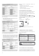
Contents
1. Read first and then... ................................................. 25
2. Scope of supply .........................................................25
3. Brief description .........................................................25
4. Physical installation ....................................................
25
4.1 Mounting on top-hat rails .....................................25
4.2 Fastening on a mounting surface .........................
26
5. Electrical connections ................................................26
6. Commissioning ...........................................................29
6.1 Technical data .......................................................
30
6.2 Programming the transducer ................................32
6.3 Operation of the binary outputs ............................
33
7. Reconfiguring the analogue outputs ..........................33
7.1 Without hardware setting change .........................33
8. Maintenance ...............................................................
34
9. Releasing the transducer ............................................34
10. Dimensional drawings ................................................
34
11. Safety notes ................................................................34
12. Declaration of conformity ...........................................36
Transducer
(Fig. 1)
1 Operating Instructions (Fig. 2) in three languages: German,
French, English
1 blank type label (Fig. 3), for recording programmed set-
tings
Fig. 1
Fig. 2
3. Brief description
The SINEAX DME 4 multi-transducers simultaneously
measure several variables of an electric power system and pro
-
cess them to produce 2 resp. 4 analogue output signals.
2 or 4 digital outputs are available for signalling limits or
energy metering. For two of the limit outputs up to three
measurands can be logically combined.
The multi-transducers are also equipped with an RS 232 serial
interface to which a PC with the corresponding software can
be connected for programming or accessing and executing
useful ancillary functions.
The usual modes of connection, the types of measured vari
-
ables, their ratings, the transfer characteristic for each output
etc. are the main parameters that have to be programmed.
Ancillary functions include a power system check, provision
for displaying the measured variable on a PC monitor, the
simulation of the outputs for test purposes and a facility for
printing nameplates.
4. Physical installation
The transducer can be mounted either on a top-hat rail or
directly onto a wall or mounting surface.
Note “Environmental conditions” in Section
“6.1 Technical data” when determining the place
of installation!
4.1 Mounting on top-hat rails
Simply clip the device onto the top-hat rail (EN 50 022) (see
Fig. 4).
Fig. 4. Mounting on top-hat rail 35 × 15 or 35 × 7.5 mm.
Camille Bauer AG
Aargauerstrasse
7
CH-5610 Wohlen/Switzerland
Phone +41 56
618 2111
Fax +41 56
618 24 58
e-Mail: info@camillebauer.com
http://www.camillebauer.com
DME 424/442 B d-f-e
122 250 09.04
Betriebsanleitung
Programmierbare Multi-Messumformer
SINEAX DME 424/442
Mode d’emploi
Convertisseurs de mesure multiples
programmables SINEAX DME 424/442
Operating Instructions
Programmable multi-transducers
SINEAX DME 424/442
Fig. 3
15+ 16–A 17+ 18–B
19+ 20–C 21+ 22–D
23+ 24–G 25+ 26–H
1. Read first and then …
The proper and safe operation of the device
assumes that the Operating Instructions
are read and the safety warnings given in
the various Sections
4. Physical installation
5. Electrical connections
6. Commissioning
11. Safety notes
are
observed.
The device should only be handled by appropriately
trained personnel who are familiar with it and authorised
to work in electrical installations.
Unauthorized repair or alteration of the unit invalidates
the warranty!