
User Manual
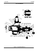
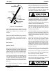
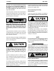
Table Of Contents

OM-00862
80 SERIES
MAINTENANCE & REPAIR
PAGE E - 6
Turn
Counterclockwise
Lathe Dog Arm
“V” Notch
Shaft Key
Impeller Shaft
Lathe Dog
Setscrew
Heavy
Bar Stock
Figure 2. Loosening Impeller
Unscrew the impeller from the shaft. Use caution
when removing the impeller; tension on the seal
spring will be released as the impeller is un
screwed.
Inspect the impeller and replace it if cracked or
badly worn. Slide the impeller adjusting shims (51)
off the impeller shaft. Tie and tag the shims, or
measure and record their thickness for ease of
reassembly.
Seal Removal
(Figures 1 and 3)
Remove the spring seat (52) and seal spring. Care
fully slide the shaft sleeve (10) and rotating portion
of the seal off the shaft (22) as a unit. Apply oil to the
sleeve and work it up under the rubber bellows.
Slide the rotating portion of the seal off the sleeve.
Carefully slide the seal plate and stationary portion
of the seal off the shaft as a unit. Lay the seal plate
on a clean, flat surface with the impeller side down
and use a suitably sized dowel to press the station
ary element and seat out of the seal plate from the
back side.
If no further disassembly is required, see Seal
Reassembly and Installation.
Shaft And Bearing Removal And Disassembly
When the pump is properly operated and main
tained, the pedestal should not require disassem
bly. Disassemble the shaft and bearings only
when there is evidence of wear or damage.
Shaft and bearing disassembly in the field
is not recommended. these operations
should be performed only in a properly‐
equipped shop by qualified personnel.
Remove the pedestal drain plug (26) and drain the
pedestal. Clean and reinstall the plug.
Remove the slinger ring (27) from the shaft. Re
move the pedestal mounting hardware from the
base. Tie and tag any shims used under the
mounting feet for leveling.
Use snap ring pliers to remove the bearing retain
ing ring (17) from the pedestal bore. Remove the
bearing shim set (16); tie and tag the shims, or
measure and record their thickness for ease of
reassembly.
Remove the setscrews (21) from the bearing re
tainer (18) and install two machine screws
(#10-32 x 1-inch long, not supplied). Pry the re
tainer from the pedestal bore using a pair of screw
drivers against the heads of the machine screws.
Do not use the machine screws to jack against the
ball bearing. Remove the machine screws and re
install the setscrews.
Press the oil seal (19) from the bearing retainer,
and remove the O‐ring (23) from the pedestal bore.
Place a block of wood against the impeller end of
the shaft and tap the shaft and assembled bear
ings (12 and 15) out of the pedestal.
Press the oil seal (11) from the pedestal bore.
After removing the shaft and bearings, clean and
inspect the bearings in place as follows.
To prevent damage during removal from