
User Manual
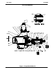
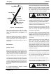
Table Of Contents

OM-0086280 SERIES
MAINTENANCE & REPAIR PAGE E - 5
such hazard, damage or diminished per
formance is not covered by the warranty.
NOTE
When appropriate recycling facilities are available,
the user should recycle components and fluids
when doing any routine maintenance / repairs and
also at the end of the pump’s useful life. All other
components and fluids shall be disposed of ac
cording to all applicable codes and regulations.
Suction Check Valve Disassembly
Before attempting to service the pump, remove the
pump casing drain plug (37) and drain the pump.
Clean and reinstall the drain plug.
To service the suction check valve, remove the suc
tion piping. Remove the nuts (49) securing the suc
tion flange (40) and the check valve assembly (42)
to the pump casing (1). Pull the check valve assem
bly from the suction port.
Inspect the check valve parts for wear or damage.
If replacement is required, remove the hardware
(46 and 47) and separate the valve gasket (44) and
weights (43 and 45).
If no further disassembly is required, see Suction
Check Valve Installation.
Pump Casing Removal
To service the impeller (2), wear plate assembly
(34) and seal assembly (3), disconnect the dis
charge piping. Remove the hardware securing the
pump casing (1) to the base.
Remove the nuts (29) securing the pump casing
and gasket set (30) to the pedestal (14) and seal
plate (9). Install a standard 5/8-11 UNC lifting eye
in the tapped hole in the top of the pump casing.
Be sure to screw the eye into the casing until fully
engaged. Use a hoist and sling of suitable capacity
to separate the casing from the seal plate and ped
estal.
Do not attempt to lift the complete pump
unit using the lifting eye. It is designed
to facilitate removal or installation of in
dividual components only. Additional
weight may result in damage to the
pump or failure of the eye bolt.
Remove the gasket set (30) from the pedestal and
seal plate. Tie and tag the gaskets, or measure and
record their thickness for ease of reassembly. Tie
and tag any leveling shims used under the casing
mounting feet to ease reassembly.
Inspect the wear plate assembly (34) and replace it
if badly scored or worn. To remove the wear plate
assembly, remove the capscrew (38) and fiber
washer (39) just below the suction port. Reach
through the suction port and disengage the hard
ware (35 and 36) from the wear plate stud. Tap t he
wear plate assembly free of the casing.
Impeller Removal
Immobilize the impeller by wedging a block wood
between the vanes. Remove the hardware (31, 32
and 33) securing the impeller to the shaft. If re
moved, install the shaft key (20). Install a lathe dog
on the drive end of the shaft (22) with the “V” notch
positioned over the shaft keyway.
With the impeller rotation still blocked, strike the
lathe dog sharply in a counterclockwise direction
(when facing the drive end of the shaft). The impel
ler may also be loosened by using a long piece of
heavy bar stock to pry against the arm of the lathe
dog in a counterclockwise direction (when facing
the drive end of the shaft) as shown in Figure 2.
Use caution not to damage the shaft or keyway.
When the impeller breaks loose, remove the lathe
dog and wood block and unscrew the impeller
from the shaft.