OM‐00862‐02 April 8, 1980 Rev. D 11‐09‐21 INSTALLATION, OPERATION, AND MAINTENANCE MANUAL WITH PARTS LIST 80 SERIES PUMP MODEL 83A3-B THE GORMAN‐RUPP COMPANY D MANSFIELD, OHIO www.grpumps.com GORMAN‐RUPP OF CANADA LIMITED D ST. THOMAS, ONTARIO, CANADA eCopyright by the Gorman‐Rupp Company Printed in U.S.A.
Register your new Gorman‐Rupp pump online at www.grpumps.com Valid serial number and e‐mail address required. RECORD YOUR PUMP MODEL AND SERIAL NUMBER Please record your pump model and serial number in the spaces provided below. Your Gorman‐Rupp distributor needs this information when you require parts or service.
TABLE OF CONTENTS INTRODUCTION . . . . . . . . . . . . . . . . . . . . . . . . . . . . . . . . . . . . . . . . . . . . . . . . . PAGE I - 1 SAFETY ‐ SECTION A . . . . . . . . . . . . . . . . . . . . . . . . . . . . . . . . . . . . . . . . . . . . PAGE A - 1 INSTALLATION - SECTION B . . . . . . . . . . . . . . . . . . . . . . . . . . . . . . . . . . . . PAGE B - 1 Pump Dimensions . . . . . . . . . . . . . . . . . . . . . . . . . . . . . . . . . . . . . . . . . . . . . . . . . . . . .
TABLE OF CONTENTS (continued) TROUBLESHOOTING - SECTION D . . . . . . . . . . . . . . . . . . . . . . . . . . . . . . PREVENTIVE MAINTENANCE . . . . . . . . . . . . . . . . . . . . . . . . . . . . . . . . . . . . . . . . . . . . . . . PUMP MAINTENANCE AND REPAIR ‐ SECTION E . . . . . . . . . . . . . . . . . STANDARD PERFORMANCE CURVE . . . . . . . . . . . . . . . . . . . . . . . . . . . . . . . . . . . . . . . . PARTS LIST: Pump Model . . . . . . . . . . . . . . . . . . . . . . . . . . . . . . . . . . . .
80 SERIES OM-00862 INTRODUCTION Thank You for purchasing a Gorman‐Rupp pump. Read this manual carefully to learn how to safely install and operate your pump. Failure to do so could result in personal injury or damage to the pump.
80 SERIES OM-00862 SAFETY ‐ SECTION A This information applies to 80 Series ba sic pumps. Gorman‐Rupp has no con trol over or particular knowledge of the power source which will be used. Refer to the manual accompanying the power source before attempting to begin oper ation. This manual will alert personnel to known procedures which require spe cial attention, to those which could damage equipment, and to those which could be dangerous to personnel.
OM-00862 unit and the National Electric Code or the applicable local code, the National or local code shall take precedence. If this pump is used with volatile and/or flammable liquids, overheating may produce dangerous fumes. Take pre cautions to ensure the area surrounding the pump is adequately ventilated. Al low the pump to cool and use extreme caution when venting the pump, or when removing covers, plates, plugs, or fittings.
0 SERIES OM-00862 INSTALLATION - SECTION B Review all SAFETY information in Section A. Since pump installations are seldom identical, this section offers only general recommendations and practices required to inspect, position, and ar range the pump and piping. specific application.
OM-00862 Only operate this pump in the direction in dicated by the arrow on the pump body and on the accompanying decal. Other wise, the impeller could become loosened from the shaft and seriously damage the pump. Refer to Rotation in OPERATION, Section C. d. Check levels and lubricate as necessary. Re fer to LUBRICATION in the MAINTENANCE AND REPAIR section of this manual and per form duties as instructed. e.
80 SERIES cause excessive vibration, decreased bearing life, and increased shaft and seal wear. If hose‐type lines are used, they should have adequate support to secure them when filled with liquid and under pressure. Gauges Most pumps are drilled and tapped for installing discharge pressure and vacuum suction gauges.
OM-00862 80 SERIES reduce the inlet velocity. Calculate the required submergence using the following formula based on the increased opening size (area or diameter). Figure 2. Recommended Minimum Suction Line Submergence vs. Velocity DISCHARGE LINES Siphoning Do not terminate the discharge line at a level lower than that of the liquid being pumped unless a si phon breaker is used in the line. Otherwise, a si phoning action causing damage to the pump could result.
80 SERIES OM-00862 either a flexible coupling or V‐belt driven system, the driver and pump must be mounted so that their shafts are aligned with and parallel to each other. It is imperative that alignment be checked after the pump and piping are installed, and before opera tion. ends are the same distance apart at all points (see Figure 3A). NOTE Check Rotation, Section C, before final alignment of the pump. Figure 3A.
OM-00862 80 SERIES from dirt, grease, oil and other foreign material which may cause slippage. Tension Measurement MISALIGNED: SHAFTS NOT PARALLEL MISALIGNED: SHAFTS NOT IN LINE ALIGNED: SHAFTS PARALLEL AND SHEAVES IN LINE Figure 3C. Alignment of V‐Belt Driven Pumps Tighten the belts in accordance with the belt manu facturer's instructions. If the belts are too loose, they will slip; if the belts are too tight, there will be excessive power loss and possible bearing failure.
80 SERIES Place the tension tester squarely on the belt at the center of the belt span. Apply force on the plunger, perpendicular to the belt span, until the bottom of the large O‐ring is even with the top of the next belt, or with the bottom of a straight edge laid across the sheaves. Read the force applied from the bottom of the small INSTALLATION OM-00862 O‐ring on the deflection force scale. Compare this force with the value shown in Table 1 or 2 and ad just the tension accordingly.
OM-00862 80 SERIES Table 1. Sheave Diameter (Inches) Deflection Force (Lbs.) Table 2. Sheave Diameter (Millimeters) Deflection Force (KG.) Belt Deflection Force Cross Section A,AX B,BX Smallest Sheave Diameter Range R.P.M. Range Uncogged Hy‐T Belts & Uncogged Hy‐T Torque Team Cogged Torque‐Flex & Machined Edge torque Team Belts Used Belt Used Belt New Belt 3.0 ‐ 3.6 1000‐2500 2501‐4000 3.7 2.8 5.5 4.2 4.1 3.4 6.1 5.0 3.8 ‐ 4.8 1000‐2500 2501‐4000 4.5 3.8 6.8 5.7 5.0 4.3 7.4 6.4 5.
OM-00862 80 SERIES OPERATION - SECTION C Review all SAFETY information in Section A. PRIMING Follow the instructions on all tags, labels and decals attached to the pump. Install the pump and piping as described in IN STALLATION. Make sure that the piping connec tions are tight, and that the pump is securely mounted. Check that the pump is properly lubri cated (see LUBRICATION in MAINTENANCE AND REPAIR).
OM-00862 80 SERIES STARTING OPERATION Consult the operations manual furnished with the power source. Lines With a Bypass If the pump has been approved for use with petro leum products, be sure the pump unit is properly grounded before operation. See GROUNDING, Section B. Rotation The correct direction of pump rotation is counter clockwise when facing the impeller. If the pump is operated in the wrong direction, the impeller could become loosened from the shaft and seriously damage the pump.
OM-00862 80 SERIES boil, build pressure, and cause the pump to rup ture or explode. If overheating occurs, stop the pump and allow it to completely cool before servic ing it. Refill the pump casing with cool liquid. lift, and should then stabilize. If the vacuum reading falls off rapidly after stabilization, an air leak exists. Before checking for the source of the leak, check the point of installation of the vacuum gauge.
OM-00862 80 SERIES curately by placing a contact‐type thermometer against the housing. Record this temperature for future reference. rect level (see LUBRICATION in Section E). Bear ing overheating can also be caused by shaft misalignment and/or excessive vibration. A sudden increase in bearing temperatures is a warning that the bearings are at the point of failing to operate properly.
80 SERIES OM-00862 TROUBLESHOOTING - SECTION D Review all SAFETY information in Section A. Before attempting to open or service the pump: 1. Familiarize yourself with this man ual. 2. Lock out or disconnect the power source to ensure that the pump will remain inoperative. 3. Allow the pump to completely cool if overheated. 4. Check the temperature before opening any covers, plates, or plugs. 5. Close the suction and discharge valves. 6. Vent the pump slowly and cau tiously. 7. Drain the pump.
OM-00862 80 SERIES TROUBLE POSSIBLE CAUSE PROBABLE REMEDY PUMP STOPS OR FAILS TO DELIVER RATED FLOW OR PRESSURE (cont.) Impeller or other wearing parts worn or damaged. Replace worn or damaged parts. Check that impeller is properly centered and rotates freely. Impeller clogged. Free impeller of debris. Pump speed too slow. Check driver output; check belts or couplings for slippage. Discharge head too high. Install bypass line. Suction lift too high. Measure lift w/vacuum gauge.
80 SERIES OM-00862 PREVENTIVE MAINTENANCE Since pump applications are seldom identical, and pump wear is directly affected by such things as the abrasive qualities, pressure and temperature of the liquid being pumped, this section is intended only to provide general recommendations and practices for preventive maintenance. Regardless of the application however, following a routine pre ventive maintenance schedule will help assure trouble‐free performance and long life from your Gorman‐Rupp pump.
OM-00862 80 SERIES PUMP MAINTENANCE AND REPAIR - SECTION E MAINTENANCE AND REPAIR OF THE WEARING PARTS OF THE PUMP WILL MAINTAIN PEAK OPERATING PERFORMANCE. STANDARD PERFORMANCE FOR PUMP MODEL 83A3-B Based on 70_ F (21_ C) clear water at sea level with minimum suction lift. Since pump installations are seldom identical, your performance may be dif ference due to such factors as viscosity, specific gravity, elevation, temperature, and impeller trim.
OM-00862 80 SERIES SECTION DRAWING PARTS PAGE Figure 1.
OM-00862 80 SERIES PARTS LIST Pump Model 83A3-B (From S/N 734045 up) If your pump serial number is followed by an “N”, your pump is NOT a standard production model. Contact the Gorman‐Rupp Company to verify part numbers. ITEM PART NAME NO. .1 2 3 4 .
OM-00862 PUMP AND SEAL DISASSEMBLY AND REASSEMBLY Review all SAFETY information in Section A. Follow the instructions on all tags, label and de cals attached to the pump. This pump requires little service due to its rugged, minimum‐maintenance design. However, if it be comes necessary to inspect or replace the wearing parts, follow these instructions which are keyed to the sectional view (see Figure 1) and the accompa nying parts lists.
80 SERIES OM-00862 such hazard, damage or diminished per formance is not covered by the warranty. to separate the casing from the seal plate and ped estal. NOTE When appropriate recycling facilities are available, the user should recycle components and fluids when doing any routine maintenance / repairs and also at the end of the pump’s useful life. All other components and fluids shall be disposed of ac cording to all applicable codes and regulations.
OM-00862 80 SERIES Turn Counterclockwise Shaft And Bearing Removal And Disassembly When the pump is properly operated and main tained, the pedestal should not require disassem bly. Disassemble the shaft and bearings only when there is evidence of wear or damage. Lathe Dog Arm “V” Notch Heavy Bar Stock Shaft Key Impeller Shaft Lathe Dog Setscrew Figure 2. Loosening Impeller Unscrew the impeller from the shaft.
80 SERIES the shaft, it is recommended that bearings be cleaned and inspected in place. It is strongly recommended that the bearings be replaced any time the shaft and bear ings are removed. Clean the pedestal, shaft and all component parts (except the bearings) with a soft cloth soaked in cleaning solvent. Inspect the parts for wear or dam age and replace as necessary. Most cleaning solvents are toxic and flammable. Use them only in a well‐ven tilated area free from excessive heat, sparks, and flame.
OM-00862 80 SERIES If heating the bearings is not practical, use a suit ably sized sleeve and an arbor (or hydraulic) press to install the bearings on the shaft. Seal Reassembly and Installation (Figures 1 and 3) Clean the seal cavity and shaft with a cloth soaked in fresh cleaning solvent. When installing the bearings onto the shaft, never press or hit against the outer race, balls, or ball cage. Press only on the inner race.
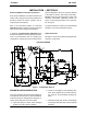
80 SERIES OM-00862 ROTATING ELEMENT SPRING STATIONARY SEAT STATIONARY ELEMENT IMPELLER IMPELLER SHAFT IMPELLER ADJUSTING SHIMS SHAFT SLEEVE SPRING SEAT SEAL PLATE BELLOWS RETAINER Figure 3. Seal Assembly This seal is not designed for operation at temperatures above 160_F (71_C). Do not use at higher operating temperatures. If the seal plate (9) was removed, lay it on a flat sur face with the impeller side facing up.
OM-00862 After the back clearance is set, secure the impeller with the hardware (31, 32 and 33). Pump Casing Installation If the wear plate assembly (34) was removed, posi tion the replacement wear plate assembly squarely against the casing shoulder and secure it with the mounting hardware (35, 36, 38 and 39). Replace the fiber washer (39) if badly worn or compressed. Remove the hardware temporarily securing the seal plate to the pedestal.
80 SERIES OM-00862 NOTE The white reflector in the sight gauge must be posi tioned horizontally to provide proper drainage. cant regularly for evidence of rust or mois ture condensation. This is especially im portant in areas where variable hot and cold temperatures are common. Under normal conditions, change the oil each 5000 hours or once each year, more frequently if the pump is operated continuously or installed in an environment with rapid temperature change.
For Warranty Information, Please Visit www.grpumps.com/warranty or call: U.S.