C OM-00772-01 December 3, 1979 Rev. A 09-17-07 INSTALLATION, OPERATION, AND MAINTENANCE MANUAL WITH PARTS LIST 80 SERIES PUMP MODEL 81 1/2E9−B THE GORMAN-RUPP COMPANY D MANSFIELD, OHIO www.grpumps.com GORMAN-RUPP OF CANADA LIMITED D ST. THOMAS, ONTARIO, CANADA eCopyright by the Gorman-Rupp Company Printed in U.S.A.
Register your new Gorman-Rupp pump online at www.grpumps.com Valid serial number and e-mail address required. RECORD YOUR PUMP MODEL AND SERIAL NUMBER Please record your pump model and serial number in the spaces provided below. Your Gorman-Rupp distributor needs this information when you require parts or service.
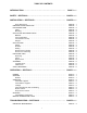
TABLE OF CONTENTS INTRODUCTION . . . . . . . . . . . . . . . . . . . . . . . . . . . . . . . . . . . . . . . . . . . . . . . . . PAGE I − 1 SAFETY - SECTION A . . . . . . . . . . . . . . . . . . . . . . . . . . . . . . . . . . . . . . . . . . . . PAGE A − 1 INSTALLATION − SECTION B . . . . . . . . . . . . . . . . . . . . . . . . . . . . . . . . . . . . PAGE B − 1 Pump Dimensions . . . . . . . . . . . . . . . . . . . . . . . . . . . . . . . . . . . . . . . . . . . . . . . . . . . . .
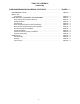
TABLE OF CONTENTS (continued) PUMP MAINTENANCE AND REPAIR - SECTION E . . . . . . . . . . . . . . . . . PERFORMANCE CURVE . . . . . . . . . . . . . . . . . . . . . . . . . . . . . . . . . . . . . . . . . . . . . . . . . . . PARTS LIST: Pump Model . . . . . . . . . . . . . . . . . . . . . . . . . . . . . . . . . . . . . . . . . . . . . . . . . . . . . . . . . . PUMP AND SEAL DISASSEMBLY AND REASSEMBLY . . . . . . . . . . . . . . . . . . . . . . . . . Pump Casing and Vane Plate Removal . . . . . . . . . . . .
80 SERIES OM−00772 INTRODUCTION Thank You for purchasing a Gorman-Rupp pump. Read this manual carefully to learn how to safely install and operate your pump. Failure to do so could result in personal injury or damage to the pump.
80 SERIES OM−00772 SAFETY - SECTION A This information applies to 80 Series basic pumps. Gorman-Rupp has no control over or particular knowledge of the power source which will be used. Refer to the manual accompanying the power source before attempting to begin operation. Because pump installations are seldom identical, this manual cannot possibly provide detailed instructions and precautions for each specific application.
OM−00772 Overheated pumps can cause severe burns and injuries. If overheating of the pump occurs: 1. Stop the pump immediately. 2. Ventilate the area. 3. Allow the pump to completely cool. 4. Check the temperature before opening any covers, plates, gauges, or plugs. 5. Vent the pump slowly and cautiously. 6. Refer to instructions in this manual before restarting the pump. 80 SERIES Never run this pump backwards. Be certain that rotation is correct before fully engaging the pump.
0 SERIES OM−00772 INSTALLATION − SECTION B Review all SAFETY information in Section A. Since pump installations are seldom identical, this section offers only general recommendations and practices required to inspect, position, and arrange the pump and piping. Most of the information pertains to a standard static lift application where the pump is positioned above the free level of liquid to be pumped. configuration, and priming must be tailored to the specific application.
OM−00772 Only operate this pump in the direction indicated by the arrow on the pump body and on the accompanying decal. Otherwise, the impeller could become loosened from the shaft and seriously damage the pump. Refer to Rotation in OPERATION, Section C. d. Check levels and lubricate as necessary. Refer to LUBRICATION in the MAINTENANCE AND REPAIR section of this manual and perform duties as instructed. e.
80 SERIES Lines near the pump must be independently supported to avoid strain on the pump which could cause excessive vibration, decreased bearing life, and increased shaft and seal wear. If hose-type lines are used, they should have adequate support to secure them when filled with liquid and under pressure. OM−00772 line, and that the openings will not permit passage of solids larger than the solids handling capability of the pump.
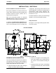
OM−00772 80 SERIES NOTE The pipe submergence required may be reduced by installing a standard pipe increaser fitting at the end of the suction line. The larger opening size will reduce the inlet velocity. Calculate the required submergence using the following formula based on the increased opening size (area or diameter). Figure 2. Recommended Minimum Suction Line Submergence vs. Velocity DISCHARGE LINES from excessive shock pressure and reverse rotation when it is stopped.
80 SERIES OM−00772 ALIGNMENT The alignment of the pump and its power source is critical for trouble-free mechanical operation. In either a flexible coupling or V-belt driven system, the driver and pump must be mounted so that their shafts are aligned with and parallel to each other. It is imperative that alignment be checked after the pump and piping are installed, and before operation. of the outer ends of the coupling hub every 90 degrees.
OM−00772 80 SERIES the belts are a matched set; unmatched sets will cause accelerated belt wear. en both v-belt and bearing life. Under-tensioning will cause belt slippage. Always keep belts free from dirt, grease, oil and other foreign material which may cause slippage. Tension Measurement Correct v-belt tension can be achieved using a vbelt tension tester and Table 1 or 2. Use the tables to find the v-belt size (cross-section), the smallest sheave diameter, the belt type for your application.
80 SERIES er at the measured belt span. Set the small O-ring on the deflection force scale to zero. Place the tension tester squarely on the belt at the center of the belt span. Apply force on the plunger, perpendicular to the belt span, until the bottom of the large O-ring is even with the top of the next belt, or with the bottom of a straight edge laid across the sheaves. INSTALLATION OM−00772 Read the force applied from the bottom of the small O-ring on the deflection force scale.
OM−00772 80 SERIES Table 1. Sheave Diameter (Inches) Deflection Force (Lbs.) Table 2. Sheave Diameter (Millimeters) Deflection Force (KG.) Belt Deflection Force Cross Section A,AX B,BX Smallest Sheave Diameter Range R.P.M. Range Uncogged Hy-T Belts & Uncogged Hy-T Torque Team Cogged Torque-Flex & Machined Edge torque Team Belts Used Belt Used Belt New Belt 3.0 - 3.6 1000-2500 2501-4000 3.7 2.8 5.5 4.2 4.1 3.4 6.1 5.0 3.8 - 4.8 1000-2500 2501-4000 4.5 3.8 6.8 5.7 5.0 4.3 7.4 6.4 5.
OM−00772 80 SERIES OPERATION − SECTION C Review all SAFETY information in Section A. Follow the instructions on all tags, labels and decals attached to the pump. This pump is designed to handle mildly corrosive industrial residues and slurries containing specified entrained solids. Do not attempt to pump liquids for which the pump, driver and/or controls have not been approved, or which may damage the pump or endanger personnel as a result of pump failure.
OM−00772 from the shaft and seriously damage the pump. Consult the operating manual furnished with the power source before attempting to start the power source. 80 SERIES sprinkler heads, and any other fixtures connected to the line. When the discharge line is completely filled, adjust the throttling valve to the required flow rate. Leakage If an electric motor is used to drive the pump, remove V-belts, couplings, or otherwise disconnect the pump from the motor before checking motor rotation.
OM−00772 80 SERIES equipment. If backflushing is absolutely necessary, liquid pressure must be limited to 50% of the maximum permissible operating pressure shown on the pump performance curve (see Section E, Page 1). Pump Vacuum Check With the pump inoperative, install a vacuum gauge in the system, using pipe dope on the threads. Block the suction line and start the pump. At operating speed the pump should pull a vacuum of 20 inches (508,0 mm) or more of mercury.
80 SERIES OM−00772 TROUBLESHOOTING − SECTION D Review all SAFETY information in Section A. Before attempting to open or service the pump: 1. Familiarize yourself with this manual. 2. Lock out or disconnect the power source to ensure that the pump will remain inoperative. 3. Allow the pump to completely cool if overheated. 4. Check the temperature before opening any covers, plates, or plugs. 5. Close the suction and discharge valves. 6. Vent the pump slowly and cautiously. 7. Drain the pump.
OM−00772 TROUBLE PUMP STOPS OR FAILS TO DELIVER RATED FLOW OR PRESSURE (cont.) 80 SERIES POSSIBLE CAUSE Suction intake not submerged at proper level or sump too small. Check installation and correct submergence as needed. Impeller or other wearing parts worn or damaged. Replace worn or damaged parts. Check that impeller is properly centered and rotates freely. Check strainer and clean if necessary. Free impeller of debris. Strainer clogged. Impeller clogged.
80 SERIES OM−00772 PREVENTIVE MAINTENANCE Since pump applications are seldom identical, and pump wear is directly affected by such things as the abrasive qualities, pressure and temperature of the liquid being pumped, this section is intended only to provide general recommendations and practices for preventive maintenance. Regardless of the application however, following a routine preventive maintenance schedule will help assure trouble-free performance and long life from your Gorman-Rupp pump.
OM−00772 80 SERIES PUMP MAINTENANCE AND REPAIR − SECTION E MAINTENANCE AND REPAIR OF THE WEARING PARTS OF THE PUMP WILL MAINTAIN PEAK OPERATING PERFORMANCE. STANDARD PERFORMANCE FOR PUMP MODEL 81 1/2E9−B Based on 70_ F (21 _ C) clear water at sea level with minimum suction lift. Since pump installations are seldom identical, your performance may be difference due to such factors as viscosity, specific gravity, elevation, temperature, and impeller trim.
OM−00772 80 SERIES PARTS PAGE SECTION DRAWING Figure 1.
OM−00772 80 SERIES PARTS LIST Pump Model 81 1/2E9−B (From S/N 334698 Up) ITEM NO.
OM−00772 PUMP AND SEAL DISASSEMBLY AND REASSEMBLY Review all SAFETY information in Section A. Follow the instructions on all tags, label and decals attached to the pump. This pump requires little service due to its rugged, minimum-maintenance design. However, if it becomes necessary to inspect or replace the wearing parts, follow these instructions which are keyed to the sectional view (see Figure 1) and the accompanying parts list.
80 SERIES OM−00772 Install the shaft key (17). Install a lathe dog on the drive end of the shaft (20) with the V" notch positioned over the shaft key. If no further disassembly is required, see Seal Reassembly and Installation. With the impeller rotation still blocked, see Figure 2 and use a long piece of heavy bar stock to pry against the arm of the lathe dog in a counterclockwise direction (when facing the drive end of the shaft). Use caution not to damage the shaft or keyway.
OM−00772 80 SERIES strongly recommended that the bearings be replaced any time the shaft and and bearings are removed. Most cleaning solvents are toxic and flammable. Use them only in a well-ventilated area free from excessive heat, sparks, and flame. Read and follow all precautions printed on solvent containers. Inspect the shaft for distortion, nicks or scratches or thread damage on the impeller end. Dress small nicks and burrs with a fine file or emery cloth. Replace the shaft if defective.
80 SERIES OM−00772 NOTE Shaft endplay should be .002 to .010 inch (0,05 to 0,25 mm). Add or remove bearing adjusting shims to obtain this endplay. Install the slinger ring (14). Install any leveling shims used under the bearing housing feet. Secure the bearing housing to the base using the previously removed mounting hardware. Seal Reassembly and Installation (Figures 1 and 3) Clean the seal cavity and shaft with a cloth soaked in fresh cleaning solvent. Most cleaning solvents are toxic and flammable.
OM−00772 80 SERIES SEAL PLATE SEAL CAP ROTATING ELEMENT SEALING WEDGE SEALING WASHERS IMPELLER IMPELLER SHAFT IMPELLER SHIMS SPACER WASHER STATIONARY SEAT SEAL SEAL SPRING RETAINER Figure 3. Seal Assembly Impeller Installation This seal is not designed for operation at temperatures above 160_F (71_C). Do not use at higher operating temperatures. Install the sealing washers and stationary seal seat in the intermediate the seal cap as shown in Figure 3.
80 SERIES Apply ‘3-M Adhesive EC-847’ or equivalent compound to the back of the vane plate, and secure the vane plate to the intermediate with the hardware (5, 6, 29 and 30). Check the impeller-to-vane plate clearance as described in Impeller Installation. Install the vane plate O-ring (35) and the pump casing gasket (26). Carefully slide the pump casing over the vane plate, and secure it to the intermediate with the nuts (8). Install the shaft key (17).
For U.S. and International Warranty Information, Please Visit www.grpumps.com/warranty or call: U.S.: 419−755−1280 International: +1−419−755−1352 For Canadian Warranty Information, Please Visit www.grcanada.com/warranty or call: 519−631−2870 THE GORMAN-RUPP COMPANY D MANSFIELD, OHIO GORMAN-RUPP OF CANADA LIMITED D ST.