BC OM-01137-OB02 May 11, 1981 Rev. B 06‐04‐2013 INSTALLATION, OPERATION, AND MAINTENANCE MANUAL WITH PARTS LIST 0 SERIES PUMP MODEL 02E3-B THE GORMAN‐RUPP COMPANY MANSFIELD, OHIO www.grpumps.com GORMAN‐RUPP OF CANADA LIMITED ST. THOMAS, ONTARIO, CANADA 2009 The Gorman‐Rupp Company Printed in U.S.A.
Register your new Gorman‐Rupp pump online at www.grpumps.com Valid serial number and e‐mail address required. RECORD YOUR PUMP MODEL AND SERIAL NUMBER Please record your pump model and serial number in the spaces provided below. Your Gorman‐Rupp distributor needs this information when you require parts or service.
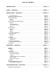
TABLE OF CONTENTS INTRODUCTION . . . . . . . . . . . . . . . . . . . . . . . . . . . . . . . . . . . . . . . . . . . . . . . . . PAGE I - 1 SAFETY ‐ SECTION A . . . . . . . . . . . . . . . . . . . . . . . . . . . . . . . . . . . . . . . . . . . . PAGE A - 1 INSTALLATION - SECTION B . . . . . . . . . . . . . . . . . . . . . . . . . . . . . . . . . . . . PAGE B - 1 Pump Dimensions . . . . . . . . . . . . . . . . . . . . . . . . . . . . . . . . . . . . . . . . . . . . . . . . . . . . .
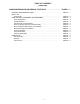
TABLE OF CONTENTS (continued) PUMP MAINTENANCE AND REPAIR ‐ SECTION E . . . . . . . . . . . . . . . . . STANDARD PERFORMANCE CURVE . . . . . . . . . . . . . . . . . . . . . . . . . . . . . . . . . . . . . . . . PARTS LIST: Pump Model . . . . . . . . . . . . . . . . . . . . . . . . . . . . . . . . . . . . . . . . . . . . . . . . . . . . . . . . . . PUMP AND SEAL DISASSEMBLY AND REASSEMBLY . . . . . . . . . . . . . . . . . . . . . . . . . Pump Disassembly . . . . . . . . . . . . . . . . . . . . . . . . . . .
0 SERIES OM-01137 INTRODUCTION Thank You for purchasing a Gorman‐Rupp pump. Read this manual carefully to learn how to safely install and operate your pump. Failure to do so could result in personal injury or damage to the pump. This pump is an 0 Series, closed impeller, self‐prim ing centrifugal model, with straight‐in suction, with out a suction check valve. It is designed to handle petroleum products or other clean liquids that do not contain large entrained solids.
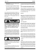
0 SERIES OM-01137 SAFETY ‐ SECTION A This information applies to 0 Series ba sic pumps. Gorman‐Rupp has no con trol over or particular knowledge of the power source which will be used. Refer to the manual accompanying the power source before attempting to begin oper ation. This manual will alert personnel to known procedures which require spe cial attention, to those which could damage equipment, and to those which could be dangerous to personnel.
OM-01137 tional Electric Code and all local codes. If there is a conflict between the instruc tions in the manual accompanying the unit and the National Electric Code or the applicable local code, the National or local code shall take precedence. If this pump is used with volatile and/or flammable liquids, overheating may produce dangerous fumes. Take pre cautions to ensure the area surrounding the pump is adequately ventilated.
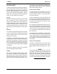
0 SERIES OM-01137 INSTALLATION - SECTION B Review all SAFETY information in Section A. Since pump installations are seldom identical, this section offers only general recommendations and practices required to inspect, position, and ar range the pump and piping. Most of the information pertains to a standard static lift application where the pump is positioned above the free level of liquid to be pumped. configuration, and priming must be tailored to the specific application.
OM-01137 AND REPAIR section of this manual and per form duties as instructed. e. If the pump and engine have been stored for more than 12 months, some of the compo nents or lubricants may have exceeded their maximum shelf life. These must be inspected or replaced to ensure maximum pump serv ice. If the maximum shelf life has been exceeded, or if anything appears to be abnormal, contact your Gorman‐Rupp distributor or the factory to deter mine the repair or updating policy.
0 SERIES SUCTION LINES To avoid air pockets which could affect pump prim ing, the suction line must be as short and direct as possible. When operation involves a suction lift, the line must always slope upward to the pump from the source of the liquid being pumped; if the line slopes down to the pump at any point along the suction run, air pockets will be created. Fittings Suction lines should be the same size as the pump inlet.
OM-01137 0 SERIES Figure 2. Recommended Minimum Suction Line Submergence vs. Velocity DISCHARGE LINES head, gradually close the discharge throttling valve before stopping the pump. Siphoning Do not terminate the discharge line at a level lower than that of the liquid being pumped unless a si phon breaker is used in the line. Otherwise, a si phoning action causing damage to the pump could result.
0 SERIES OM-01137 When checking alignment, disconnect the power source to ensure that the pump will remain inoperative. Figure 3B. Aligning Non‐Spider Type Couplings Adjusting the alignment in one direction may alter the alignment in another direc tion. check each procedure after altering alignment. Coupled Drives When using couplings, the axis of the power source must be aligned to the axis of the pump shaft in both the horizontal and vertical planes.
OM-01137 Tighten the belts in accordance with the belt manu facturer's instructions. If the belts are too loose, they will slip; if the belts are too tight, there will be excessive power loss and possible bearing failure. Select pulleys that will match the proper speed ra tio; over speeding the pump may damage both pump and power source. 0 SERIES Ideal drive belt tension is the lowest tension at which the belt will not slip under peak load condi tions. Do not over‐tension drive belts.
OM-01137 0 SERIES OPERATION - SECTION C Review all SAFETY information in Section A. Follow the instructions on all tags, labels and decals attached to the pump. coming liquid to evacuate the air. After the pump and piping system have completely filled, evacu ate any remaining air pockets in the pump or suc tion line by loosening pipe plug or opening bleeder valves. Once the pump casing has been filled, the pump will prime and reprime as necessary.
OM-01137 ature supplied with the motor for specific instruc tions. OPERATION 0 SERIES Overheating can occur if operated with the valves in the suction or discharge lines closed. Operating against closed valves could bring the liquid to a boil, build pressure, and cause the pump to rup ture or explode. If overheating occurs, stop the pump and allow it to cool before servicing it. Refill the pump casing with cool liquid.
OM-01137 0 SERIES Before checking for the source of the leak, check the point of installation of the vacuum gauge. STOPPING Never halt the flow of liquid suddenly. If the liquid being pumped is stopped abruptly, damaging shock waves can be transmitted to the pump and piping system. Close all connecting valves slowly. After stopping the pump, lock out or disconnect the power source to ensure that the pump will re main inoperative. Checking bearing temperatures by hand is inaccu rate.
OM-01137 0 SERIES TROUBLESHOOTING - SECTION D Review all SAFETY information in Section A. Before attempting to open or service the pump: 1. Familiarize yourself with this manual. 2. Disconnect or lock out the power source to ensure that the pump will remain inoperative. 3. Allow the pump to completely cool if overheated. 4. Check the temperature before open ing any covers, plates, or plugs. 5. Close the suction and discharge valves. 6. Vent the pump slowly and cautiously. 7. Drain the pump.
OM-01137 TROUBLE PUMP STOPS OR FAILS TO DELIVER RATED FLOW OR PRESSURE (cont.) PUMP REQUIRES TOO MUCH POWER PUMP CLOGS FREQUENTLY EXCESSIVE NOISE BEARINGS RUN TOO HOT PAGE D - 2 0 SERIES POSSIBLE CAUSE PROBABLE REMEDY Suction intake not submerged at proper level or sump too small. Check installation and correct submergence as needed. Impeller or other wearing parts worn or damaged. Replace worn or damaged parts. Check that impeller is properly centered and rotates freely. Impeller clogged.
OM-01137 0 SERIES PREVENTIVE MAINTENANCE Since pump applications are seldom identical, and pump wear is directly affected by such things as the abrasive qualities, pressure and temperature of the liquid being pumped, this section is intended only to provide general recommendations and practices for preventive maintenance. Regardless of the application however, following a routine pre ventive maintenance schedule will help assure trouble‐free performance and long life from your Gorman‐Rupp pump.
0 SERIES OM-01137 PUMP MAINTENANCE AND REPAIR ‐ SECTION E MAINTENANCE AND REPAIR OF THE WEARING PARTS OF THE PUMP WILL MAINTAIN PEAK OPERATING PERFORMANCE. STANDARD PERFORMANCE FOR PUMP MODEL 02E3-B Based on 70 F (21 C) clear water at sea level with minimum suction lift. Since pump installations are seldom identical, your performance may be dif ference due to such factors as viscosity, specific gravity, elevation, temperature, and impeller trim.
OM-01137 0 SERIES SECTION DRAWING PARTS PAGE Figure 1.
0 SERIES OM-01137 PARTS LIST Pump Model 02E3-B (From S/N 284632N Up) If your pump serial number is followed by an “N”, your pump is NOT a standard production model. Contact the Gorman‐Rupp Company to verify part numbers. ITEM NO.
OM-01137 PUMP AND SEAL DISASSEMBLY AND REASSEMBLY Review all SAFETY information in Section A. Follow the instructions on all tags, label and de cals attached to the pump. This pump requires little service due to its rugged, minimum‐maintenance design. However, if it be comes necessary to inspect or replace the wearing parts, follow these instructions which are keyed to the sectional view (see Figure 1) and the accompa nying parts list.
0 SERIES OM-01137 impeller vanes, being careful not to damage the vanes. Disengage the impeller nut (27). stationary element and seat out of the intermediate from the back side. Install the shaft key (15). Install a lathe dog on the drive end of the shaft (16) with the “V” notch posi tioned over the shaft key. Remove the slinger ring (20).
OM-01137 flammable. Use them only in a well ven tilated area free from excessive heat, sparks, and flame. Read and follow all precautions printed on solvent contain ers. Clean the bearings thoroughly in fresh cleaning solvent. Dry the bearings with filtered compressed air and coat with light oil. The bearings must be kept free of all dirt and foreign material. Failure to do so will greatly shorten bearing life. Do not spin dry bearings.
0 SERIES OM-01137 Install the same thickness of bearing adjusting shims (18) as previously removed. Reinstall the re taining ring (17) and check the shaft endplay. NOTE Shaft endplay should be .002 to .010 inch (0,05 mm to 0,25 mm). Add or remove bearing adjusting shims to obtain this endplay. Install the slinger ring (20) and shaft key (15). Seal Reassembly and Installation Clean the seal cavity and shaft with a cloth soaked in fresh cleaning solvent. Most cleaning solvents are toxic and flammable.
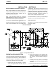
OM-01137 0 SERIES RETAINER BEARING HOUSING SPRING SPRING RETAINER IMPELLER ROTATING ELEMENT IMPELLER SHAFT IMPELLER SHIMS STATIONARY ELEMENT BELLOWS STATIONARY SEAT DRIVE BAND Figure 3. Seal Assembly Subassemble the rotating element into the retainer and bellows. Lubricate the I.D. of the bellows with water and slide this subassembly onto the shaft until the polished faces contact. Install the seal operation at spring and spring retainer.
0 SERIES OM-01137 C D D 2 B 2 A E B Step 1 Step 2 A+ B 2 - C+ D 2 Step 3 =E Figure 4. Centering Impeller Within Vane Plate Scroll Install the correct thickness of impeller shims (14) and screw the impeller onto the shaft until fully seated. Apply “Loctite Threadlocker No. 242” or equivalent compound to the impeller shaft threads and se cure the impeller with the impeller nut (27). Torque the nut to 30 ft. lbs. (360 in lbs. or 4,15 m. kg.).
For U.S. and International Warranty Information, Please Visit www.grpumps.com/warranty or call: U.S.: 419-755-1280 International: +1-419-755-1352 For Canadian Warranty Information, Please Visit www.grcanada.com/warranty or call: 519-631-2870 THE GORMAN‐RUPP COMPANY MANSFIELD, OHIO GORMAN‐RUPP OF CANADA LIMITED ST.