MT IE GB INSTRUCTIONS FOR USE, INSTALLATION, AND CONNECTION GLASS CERAMIC INDUCTION BUILT-IN COOKING HOB
GLASS CERAMIC INDUCTION BUILT-IN COOKING HOB Dear customer ! Built-in glass ceramic induction hob is intended solely for use in households. Our products are packed in environment-friendly materials which can be safely recycled, disposed of, or destroyed. Respective packaging materials are labeled accordingly. When the appliance is outdated and you intend to dispose of it, please make sure this is done in an environment-friendly manner.
TABLE 492203 IMPORTANT - READ BEFORE USING THE APPLIANCE ......................................... 4 Safety percautions........................................................................................................................4 Warnings............................................................................................................................................5 CERAMIC-GLASS COOKTOP .......................................................................................
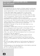
IMPORTANT - READ BEFORE USING THE APPLIANCE Safety percautions • This appliance can be used by children aged from 8 years and above and persons with reduced physical, sensory or metal capabilities or lack of experience and knowledge if they have been given supervision or instruction concerning use of the appliance in a safe way and understand the hazards involved. Children shall not play with the appliance. Cleaning and user maintenance shall not be made by children without supervision.
Warnings • The appliance may only be connected to the power mains by an authorized service technician or expert. • Tampering with the appliance or non-professional repair thereof may result in risk of severe injury or damage to the product. Any repairs may only be carried out by an authorized service technician or expert. • The appliance is intended solely for cooking. Do not use it for any other purpose, e.g. for room heating. Do not place empty cookware on the cooking zones.
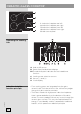
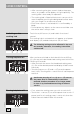
CERAMIC-GLASS COOKTOP 1. Induction hotplate rear left 2. Induction hotplate rear right 3. Induction hotplate front left 4. Induction hotplate front right 5. Hob control panel Operating the cooking hob A Hob on/off sensor B Power level/residual heat displays B1 The decimal point indicates the activated timer function C Cooking zone selection sensors E Sensor (-) and (+) H Clock display Induction hotplate function principle 492203 6 • Four cooking zones are integrated into the glass ceramic hob.
• Glass ceramic hotplate is not heated directly, but only by return heat transmitted by the dish. This heat figures as “remaining heat” after the hotplate is turned off. The induction hotplate generates heat from the induction coil, installed underneath the ceramic glass surface. The coil creates magnetic field at the bottom of the dish (which can me magnetized) which in turn originates whirling flows of current which then heat the hotplate.
Cooking zone Minimum pan bottom diameter Ø 160 mm Ø 130 mm Ø 180 mm Ø 130 mm Ø 200 mm Ø 145 mm The magnet test Using a small magnet, it is possible to check whether the bottom of your cookware can be magnetized .Use only cookware to which the magnet will stick. Pan recognition One of the many advantages of an induction cooking hob is the pan, or cookware, recognition.
Power regulation Power setting 0 1-2 3 4-5 6 7-8 Cooking zone heat power can be set to ten different levels. The table lists some examples of use for each level.
HOB CONTROL • After connecting the glass ceramic hob to the power mains, all symbols on the display will light up briefly. The cooking hob is then ready for operation. • The cooking hob is fitted with electronic sensors which are activated by touching the designated surface areas with your finger for at least one second. • Each time a sensor is activated, this is confirmed by a beep. • Do not place any objects on the sensor area. Make sure the sensor area is always clean.
Powering off the cooking hob • The cooking hob may be switched off anytime by touching the on/off sensor (A). All settings will be deleted, except for the minute minder (see section »Timer«). Engaging the control unit lock / child safety lock By activating the control unit lock, you can prevent the operation or use of the cooking zones. Thus, the control unit lock also works as a child safety lock. Activating the child lock • The hob must be switched off.
Note: The front left and the rear right cooking zones feature the power boost function. In a cooking zone with this function, extra power is activated for five minutes; then, the zone switches to level 9. Activating the Power Boost • Press the relevant sensor (C) to select the cooking zone. Use the »–« or »+« sensor (E) to choose the power level 9; then, press »+« immediately. »P« will appear on the power level display.
• Induction cooking hob is also fitted with a builtin overheating protection device that protects the electronic parts from damage. The protection device operates at several levels. When the cooking zone temperature increases considerably, the cooking power is reduced automatically. If this is not enough, the power of currently heated cooking zones is reduced further or shut off entirely. In this case, »E2« will be indicated on the display.
• Value can be set from 01 to 99 minutes. Shut-off timer can be set for each cooking zone. • To check the remaining time, select the corresponding cooking zone and activate the timer function. Press the »–« or »+« sensor (E) to change the setting. (Press the »–« and »+« sensor (E) simultaneously and sequentially to choose between active settings.) • When the set time expires, »00« will flash on the display; in addition, relevant decimal point will flash at the shut-off timer. A short beep will be heard.
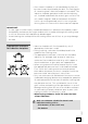
CLEANING AND MAINTENANCE OF CERAMICGLASS HOB Cleaning Figure 1 Figure 2 Figure 3 After each use of the glass-ceramic hob, wait for it to cool down and clean it; otherwise, even the smallest food residue will be burnt onto the hot surface next time you use the appliance. For regular cleaning and maintenance of the glass-ceramic surface, use special conditioning agents which form a protective layer on the surface, shielding it from dirt.
Figure 5 Sugar and sugar-laden food may permanently damage the glass-ceramic surface (Figure 5); therefore, they should be removed from the glass-ceramic surface as soon as possible, although the cooking zone may still be hot (Figure 4). Any change in the color of the glass-ceramic surface does not affect its operation or the stability of the surface.
Before inserting the appliance into the opening in the kitchen worktop, the supplied foam gasket must be attached to the lower side of the glass ceramic (glass) cooking hob (see figure above). Do not install the appliance without the foam gasket! The gasket should be attached to the appliance in the following way: - Remove the protective film from the gasket. - Then, attach the gasket to the lower side of the glass, approximately 2-3 millimetres from the edge (as shown in the figure).
Worktop cutout dimensions - SIVK6 • Cooking hobs can be installed into worktops that are 30 to 50 mm thick. • If the board is thicker than 40 mm, its inner edge should be trimmed, or ground (Figure A). Thus, sufficient air circulation will be provided. • If the thickness of your counter top exceeds 30 mm, then the opening for the hob should be made in the middle of the oven, with sufficient clearance from the front edge of the counter top so that the induction hob does not touch the oven shield.
• To enable normal operation of electronic components of the induction hob, sufficient air circulation must be provided. A Lower kitchen cabinet with a drawer • An opening at least 140 mm high must be provided on the back wall of the cabinet, along its entire width. Furthermore, a minimum of 6 mm clearance must be provided at the front side, along the entire width of the cabinet. • The hob is fitted with a fan located in its lower part.
B Lower kitchen cabinet with an oven • Installing the oven under an induction hob is possible with oven types EVP4.., EVP2.., which are fitted with a cooling fan. Before installing the oven, the rear wall of the kitchen cabinet should be removed. Furthermore, a minimum of 6 mm clearance should be provided at the front side, along the entire width of the cabinet.
The appliance is designed for two-phase connection; it can also be connected to a single phase. • Two-phase connection Insert the jumpers between N1 and N2. • Single-phase connection Insert one jumper between N1 and N2 and one jumper between L1 and L2. Connection may be carried out by means of: • rubber coated connection cables, model H05 RR-F 4x1,5 with yellow-green earthing cable; • PVC insulated connection cables, model H05 VV-F 4x1,5 with yellow-green earthing cable; or any other suitable cables.
CONNECTION TO THE POWER SUPPLAY • Connections may be carried out by a qualified technician only. The earthing protection must comply with the standing regulations. • Connection terminals are revealed when the connection box cover is removed. • Prior any attempted connection check that the voltage indicated on the rating plate is in line with your home power supply. • The rating plate is located underneath the appliance. • The appliance is manufactured for use with the power supply voltage 230 V ~.
Single-phase connection with total power limiter (only in model with four cooking zones and without the bridge function) • If your home main fuse does not allow 32-ampere current, then the function of total power limiter can be activated on the hob so that the current never exceeds 16 A. • If you activate the total power limiter, then the power of each cooking zone may only be increased until total power reaches the limit. When the limit is reached, the hob will beep and the setting display will flash.
TECHNICAL INFORMATION Rating plate A B C D E F G Serial number Code Model Type Trademark Technical information Compliance indications / symbols WE RESERVE THE RIGHT TO ALTER THE SPECIFICATIONS WITH NO INFLUENCE TO THE OPERATION OF THE APPLIANCE. 492203 Instructions for use of the appliance can also be found on our website at www.gorenje.com / < http://www.gorenje.
492203
492203 26
SIVK_BI3 en (10-14)