
Operation Manual


8
until a regular minimum flame is obtained.
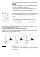
3. Re-assemble the knob and verify burner flame stability (when quickly rotating the
hand from maximum to minimum position the flame must not shut off).
4. Repeat the operation on all gas taps.
Instructions for liquid gas (LPG: G30, G31)
Tighten the screw on the side of the tap, rod clockwise completely.
Warning: these tasks may only be carried out by a qualified technici
an, authorized by the
gas distributing company or authorized service center!
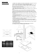
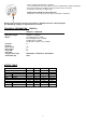
TECHNICAL INFORMATION (TABLE 1)
GW65CLI
---
GW65CLB
Appliance dimension
(mm)
600
Operating voltage
220-240 V~, 50/60 Hz
Burner
A: Auxiliary burner (1,0kW)
SR: Semirapid burner (1,75kW)
R: Rapid burner (3,0kW)
TC: Bruciatore Tripla corona (3,8kW)
Front left
R
Rear left
-
Front
central
SR
Rear
central
A
Front right
TC
Rear right
-
Category
Gas
usage
G20/20mbar
, G30/30mbar , G25/20mbar
Total Power
(W)
9550
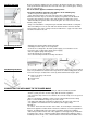
NOZZLE TABLE
Burner
A
SR
R
TC
Rated heat output (kW)
1.00 1.75 3.00
3.80
Ø INJECTOR
(mm)
G30/G31
28..30/30-37mbar
0.50 0.65 0.85 0.98
G20 20mbar
0.72 - X 0.97 - Z 1.28 - H3 1.35 - K
G25 20mbar
0.77 - F1 1.00 - Y 1.26 - Y 1.52 - F3
Ø BY
-
PASS
(mm
)
G30/G31
28..30/30-37mbar
0.27 0.34 0.42 0.62
G20 20mbar
REG. REG. REG. REG.
G25 20mbar
REG. REG. REG. REG.