
Operation Manual


7.5.201521211818
18
a)
b)
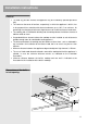
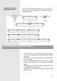
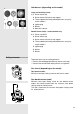
Hob burners (depending on the model)
Large and auxiliary burner
a) 1. Burner crown cap
2. Burner crown with burner cap support
3. Thermal probe (thermally protected burners only, only
certain models)
4. Ignition plug
5. Nozzle
6. Bowl of the burner
Double burner (wok) - certain models only
b) 1. Burner cup WOK
2. Burner crown cap
3. Burner crown with burner cap support
4. Thermal probe (thermally protected burners only, only
certain models)
5. Ignition plug
6. Nozzle
7. Nozzle
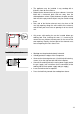
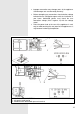
To provide access to the setting elements:
• Remove the cooktop grid and burner crowns with caps,
• Remove the control knobs along with the seal gaskets.
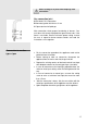
Gas faucet (depending on the model)
Twin burner model:
Minimum heat input setting screw for twin burner model.
One double burner (wok)
Minimum heat input setting screw for one double burner
model: Gas faucet thread holds the minimum heat power
setting screw for interior burner.
The side is fitted with the minimum heat power setting screw
for exterior burner.
Setting elements