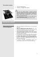
EN INSTRUCTIONS FOR USE, MOUNTING AND CONNECTION Integrated gas hob
Integrated gas hob EN Dear Buyer, This integrated gas hob is manufactured for household use. Our appliances are packed in the environmentally friendly materials which may be recycled, deposited or destroyed without any hazard to the environment. Such packaging materials are also labeled accordingly. Once the life cycle your appliance is over, make sure not to pollute the environment, and deliver it to the authorized collectors of old household appliances.
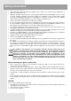
Safety precautions Only certified specialist can build in the appliance into a furniture set, connect it to gas distribution net and to the electric power net. During the operation of gas burners the room may be filled with extra heat and humidity, so it is necessary to assure adequate ventilation. Occasional opening of the window or door should provide enough exchange of air.
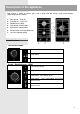
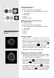
Description of the appliance Hob surface is made of ceramic glass and is fitted with gas burners and control buttons (depending upon the model). 1. Rear burner – large (B) 2. Front burner – small (A1) 3. Double burner (Wok) 4. Front burner control button 5. Rear burner control button 6. Control button of the double burner 7.
The location of grating 1. Cast iron cooking grating. 2. Centering – setting pin of the grating. The cast iron cooking grating is heated up during appliance operation and remains hot during some time even after extinction of the gas burners. Therefore be always careful (also at manipulation with the control knobs), for to prevent burning! The cooking grating at the burner can be loaded with an utensil of total weight of 15 kg.
a) Large and auxiliary burner a) 1. Burner crown cap 2. Burner crown with burner cap support 3. Thermal probe (thermally protected burners only, only certain models) b) 4. Ignition plug 5. Nozzle 6. Bowl of the burner Double burner (wok) - certain models only b) 1. Burner cup WOK 2. Burner crown cap 3. Burner crown with burner cap support 4. Thermal probe (thermally protected burners only, only certain models) 5. Ignition plug Ignition and operation of burners 6. Nozzle 7.
Always push the button in before starting to turn it! Burner type Large (3kW) Auxiliary (1 kW) Double (WOK) - interior flame (1kW) Double (WOK) - all flame Dish diameter 220 - 260mm 120 - 180mm 120 - 180mm 220 - 300mm To ignite the burner, press the selected burner button and turn it to the maximum power position (large flame symbol). Electric spark from the ignition device ignites the gas. If the ignition device is out of order (power failure or humidity), use a match or a lighter to ignite the gas.
Cookware Selection of the adequate dish size ensures optimized cooking time and consumption of gas. Diameter of the dish is of utmost importance. The flame reaching over the edge of the small diameter dish may destroy the dish, while the consumption of gas is increased. Gas needs oxigen for burning. In case of excessively large dish diameter the oxigen supply is insufficient, consequently reducing the burning capacity.
Stubborn stains should be removed with wet cloth and then rubbed dry with a dry cloth to the brilliance. Never use such cleaners for cleaning of aluminum. Clean plastic and coated surfaces with liquid non-abrasive cleaning agents using soft cloth. Gas grid, cooking area and burner components should be cleaned with warm water and mild detergent for manual washing of dishes. Thermal element and ignition device should be cleaned with soft brush.
Pattern marks can be erased by the use of aggressive cleansing agents or rough and damaged cookware bottoms (Fig. 2). fig. 2 fig. 3 fig. 4 Minor stains are removed with moist soft cloth; after that the surface should be wiped dry (Fig. 3). Water stains are removed with gentle vinegar solution, but you must not wipe the frame with it (certain models only), since it may lose its glow. Never use any aggressive sprays or limestone removers (Fig. 3).
Troubleshooting guide Repairs may be done by qualified personnel only. Any unskilled attempt to repair the appliance is extremely dangerous. Before attempting any repairs disconnect the appliance from the mains by removing the fuse or unplugging the mains lead from the mains socket. Any unskilled attempts and/or repairs may cause electric shock and short circuit. To avoid such injuries any repairs may be performed only by qualified personnel or after sales service.
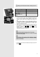
Installation instructions Caution! To avoid any possible hazard, the appliance may be installed by qualified personnel only. The veneer or the cover of furniture, respectively, in which the appliance is built in, has to be prepared from materials with thermal endurance up to 100° C as minimum, for preventing the changing of color and shape because of insufficient thermal endurance. The cooking hob is intended for building into the worktop above the kitchen element of 600 mm width or more.
The appliance may be installed in any worktop with a thickness from 30 mm to 50 mm. Bottom kitchen element must not have a drawer. It must be fitted with a horizontal plate 150 mm away from the worktop bottom surface. Space between the plate and the hob must be empty and no objects may be stored or kept there. Rear side of the kitchen element must also have a 150 mm high opening along the entire width of the element, and the front part must have an opening of no less than 6 mm.
Installation of several glass-ceramic hobs When installing several glassceramic hobs it is necessary to separate them with intermediary short strip (to be purchased separately 286696). 286696 Connecting the hob to the mains Connections may be carried out by a qualified technician only. The earthing protection must comply with the standing regulations. Connection terminals are revealed when the connection box cover is removed.
The electric wiring should be equipped with a circuit breaker able to isolate the appliance from the mains in all points, with the distance between terminals of at least 3 mm in open position. This may be done by means of fuses, safety switches, etc. The connection should be selected in accordance with the declared charge capacity of the mains and the fuse power. Such appliances are allowed to be mounted on one side next to a high kitchen cabinet, the height of which may exceed that of the appliance.
Improper connection may damage parts of the appliance. Such damages are not covered by warranty! Before attempting any connections check whether voltage indicated on the rating plate agrees with the installation in your home. Authorized person must check the user connection voltage (230 V against N) with the voltage meter! Place the power lead at the rear of the appliance in such way to avoid touching the rear panel of the appliance as it may become hot during the operation.
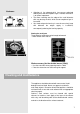
Gas connection Safety precautions Connection 7.5.201521211616 Connections may be carried out by a qualified technician only. The appliance must be connected in accordance with the standing ragulations, and it may be used only in well ventilated rooms. Before any attempt to connect the appliance read carefully the instructions! Before installation and connection check if the local connection specifications (type and pressure of gas) correspond to the specifications of the appliance.
Check sealing of all joints and couplings after connection. Gas connection joint A EN 10226 R1/2 connection B Nonmetal gasket of thickness 2 mm C Pipe extension for liquid gas After connection check proper functioning of burners. Gas must burn with clearly displayed blue-green flame hubs. If the flame is not stable, increase minimum power setting. Instruct the user in regard to burner button controls and read the instructions or use together.
Hob burners (depending on the model) a) Large and auxiliary burner a) 1. Burner crown cap 2. Burner crown with burner cap support 3. Thermal probe (thermally protected burners only, only b) certain models) 4. Ignition plug 5. Nozzle 6. Bowl of the burner Double burner (wok) - certain models only b) 1. Burner cup WOK 2. Burner crown cap 3. Burner crown with burner cap support 4. Thermal probe (thermally protected burners only, only certain models) 5. Ignition plug 6. Nozzle 7.
Nozzle chart - glas ceramic hob Type of gas Auxiliary burner Number Wobbe max 1 95,2 72X 690771 min 0,36 34,4 • max 3 285,6 128H3 438244 min 0,76 72,4 • 1 72,7 50 690780 0,36 26,2 24 3 218,1 85 690782 0,76 55,3 33 Natural gas H Ws= 45,7÷54,7 MJ/m3 Natural gas E, E+ Ws= 40,9÷54,7 MJ/m3 G 20, p = 20 mbar Liquid gas 3+, 3B/P Ws= 72,9÷87,3 MJ/m3 G 30, p = 30 mbar Nominal heat input (kW) Consumption (l/h) Nozzle mark (1/100mm) Nozzle code Nominal heat input (kW) Consumption (g/h) Nozzle mark (1/100mm
GB Type of gas Double burner (Wok) Number Wobbe min intermediat e and exterior flame 1,9 181,0 max mininterior flame Nominal heat input (kW) Consumption (l/h) Nozzle mark (1/100mm) Nozzle code 0,8/4,2 76,2/400,2 70H1 147H3 438921 438922 0,36 34,3 Nominal heat input (kW) Liquid gas 3+, 3B/P Ws= 72,9÷87,3 MJ/m3 Consumption (g/h) G 30, p = 28-30 mbar Nozzle mark (1/100mm) Nozzle code Nominal heat input (kW) Liquid gas 3+, 3B/P Ws= 72,9÷87,3 MJ/m3 Consumption (g/h) G 31, p = 37 mbar Nozzle mark (1/
Technical information Type Model 4108 GC341UC 4109 GCW341UC Appliance dimensions (height/width/depth) mm 46/300/510 46/300/510 230 V ~ 230 V ~, 50 Hz A1 = small burner B = large burner 230 V ~ 230 V ~, 50 Hz Mains voltage Operating voltage Double burner (Wok) Front 1kW / A1 \ Rear 3kW / B \ 4,2 Cooking burners altogether (kW) Cookeng burners altogether - liquid gas (g/h) Gas type is indicated on the rating plate.
4108, 4109 / EN 2015 05 15 / SAP 458293