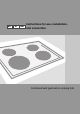
MT IE GB Instructions for use, installation, and connection Combined and gas built-in cooking hob
Combined and gas built-in cooking hob Dear customer! Combined and gas built-in hob is intended for use in households. Our products are packed in environment-friendly materials which can be recycled, disposed of, or destroyed without imposing any burden on the environment. Instructions for use Instructions for use are intended for the user. They describe the appliance and its operation.
Important warnings • Installation of the appliance into a kitchen worktop and its connection to the power mains and the gas supply may only be performed by an adequately qualified technician. • When the appliance is in use, additional heat and moisture are emitted into the room. When the appliance is used for a prolonged period of time at a high performance level, intensive ventilation or use of kitchen hood may is required in the room where the appliance is installed.
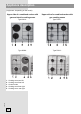
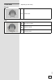
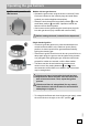
Appliance description (equipment - depending on the model) Upper side of a combined cooker with gas and electric cooking zones Upper side of a combined cooker with gas cooking zones Type KVK4... Type PVK4... Type KVK6... Type PVK6... 1. 2. 3. 4. 5.
Control knob (depending on the model) Electric 1- 6 power levels Gas gas valve is closed maximum power 252569 minimum power 5
Cooking zones A) Electric cooking zones Turn on the cooking zones for 3 to 5 minutes and select the maximum power level; some fumes may be discharged from the hob. This way, the protective cover on the cooking hob will reach its maximum solidness.
Energy saving • Pan bottom diameters should match the diameter of the cooking zone. If the pan is too small, some heat is wasted; furthermore, using a too small pan can damage the cooking zone. • Whenever possible given the cooking process, use a lid. • The pan should be appropriately sized given the quantity of food prepared. Preparing a small quantity of food in a large pan will cause a waste of energy. • Dishes that take a long time to cook should be prepared in a pressure cooker.
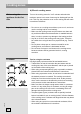
Cookware • Correctly selected cookware will enable optimum cooking time and gas consumption. Pan diameter is the most important parameter. • Flames that reach over the edge of a pan that is too small, can damage the cookware; furthermore, gas consumption is higher in such cases. • For combustion, the gas also needs air. If a pan is too large, air supply to the burner is insufficient; as a result, combustion effect is lesser.
Operating the gas burners Models with two gas burners: • Operate the gas burners using the knobs on the hob. Power levels are indicated on the knobs by large and small flame symbols (see section Appliance description). • Rotate the knob through the large flame position ( ) to the small flame position ( ) and back. Operation interval lies between the two flame symbols. • Gas burners can be ignited using the electric spar plug built into each gas burner (only available with some models).
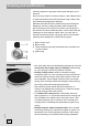
Cleaning and maintenance Clean the appliance using warm water, liquid detergent, and a soft cloth. Do not use any abrasive or sharp utensils or other objects. Burnt or dried food residues should be moistened using a damp cloth and softened with appropriate detergent. Stainless steel parts should be cleaned using special-purpose detergents. Use a dry, highly-absorbent cloth to apply a thin layer of detergent on a dry and cool surface, and rub gently in the direction of surface treatment pattern.
Do not use aggressive utensils for cleaning the dishes, as these will scratch the rings. Gas cooking zones To clean the grid, cooking hob surface, and parts of the burner, use hot water with some dishwashing detergent. Clean the thermo-element and the spark plug with a soft brush. These parts must be kept impeccably clean, as only then will they operate correctly. Clean the crown and the burner cover. Be particularly careful to keep all exit slots on the crown clean and unobstructed.
What happened...? The burners will not burn The flame is uneven / unstable The flame from the burners suddenly changes Burner ignition takes more time The flame is extinguished shortly after ignition The grid has discolored in the burner area? Possible cause Flame is uneven due to a wrong gas power setting. Wrongly assembled parts of the kitchen hob Wrongly assembled parts of the kitchen hob Knob pressed too short or to weakly.
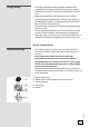
• The distance between the appliance edge and the adjacent tall kitchen furniture element should amount to no less than 100 mm. • Use of massive wood decoration plates or boards on the worktops behind the cooking hob is permitted, if the minimum distance remains the same as indicated in the installation drawings. • Minimum distance between the built-in cooking hob and the rear wall is indicated on the installation drawing. • Cooking hobs can be installed into worktops that are 30 to 50 mm thick. Type KVK4.
• Only type EVP4, EVP2…, ovens fitted with a cooling fan may be installed underneath this cooking hob. • Before installing an oven, the rear wall of the kitchen furniture element should be removed in the area of the cooking hob cutout. Furthermore, a gap of at least 6 mm should be left at the front side. Installation procedure • The worktop should be installed completely horizontally. • The cutoff surfaces should be appropriately protected.
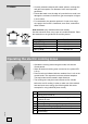
Connecting the appliance to the power mains Important warnings • • • • • • • • • The appliance may only be connected by an authorized skilled technician. Electric system protection should comply with all relevant regulations. The connection clips can be accessed when the connection clip covers are opened / removed. Before connecting the appliance, make sure the voltage indicated on the rating plate is consistent with the voltage in your home circuit.
230V~ L1 N PE NOTE: Connection bridges are already installed on their respective places on the clip. Screws of the connection terminals are open, which means they do not have to be unfastened or unscrewed any further. When fastening the screws, you may hear a slight ‘click’, which means that the screws should be fastened / screwed in completely. The following can be used for connection: • Type H05 RR-F 4×1.
• On the lower side, the cooking hob is fitted with a gas connection plug with a EN ISO 10226-1 / -2 or EN ISO 228-1 (Depending on the country-specific connection regulations.) thread. • Also supplied with the appliance is an adapter for liquid gas and a non-metal gasket. • When connecting, the knee R ½ should be held firmly to prevent it from rotating. • For sealing of the connection joints, use a non-metal approved gaskets and approved sealants. • The gaskets should only be used once.
regulation screw for minimum thermal load as far as it will go, in order to attain minimum thermal load. • When adapting the appliance to natural gas, release the minimum thermal load regulation screw in order to attain minimum thermal load, but do not rotate it by more than 1.5 turns.
Nozzle table gas type, pressure Auxiliary burner Standard Wobe Number Natural gas H Wo=45,7÷ 54,7 MJ/ m3, Natural gas E , Natural gas E+ Wo=40,9÷54,7 MJ/m3 G20, p=20mbar Nom. therm. load (kW) Liquid gas 3B/P Wo=72,9÷87,3MJ/m3 G30 p=30 mbar Nom. therm.
Technical characteristics Rating plate A B C D E F G H Serial number Model Type Trademark Code Technical information Compliance indications / symbols Factory settings for gas type WE RESERVE THE RIGHT TO MAKE ANY CHANGES THAT DO NOT AFFECT THE FUNCTIONALITY OF THE APPLIANCE.