Transform any computer into a powerful automotive diagnostic scan tool with performance analysis capabilities! ~ Visit us online at MyScanTool.com ~ ________________________________________________________________________ Copyright © 2005-2006 by Gore Research. All Rights Reserved.
Table of Contents Warnings ............................................................................................................................. 3 Introduction......................................................................................................................... 4 Getting Started with ProScan.............................................................................................. 5 Hardware and Software Requirements .............................................................
Warnings Never use ProScan while driving! You should never attempt to use ProScan while operating a moving vehicle. If you need to monitor sensor information while driving, it is strongly recommended that you have a passenger operate ProScan. If you don’t have a helping passenger, use ProScan’s logging feature so that you can playback the collected data once you have safely parked your vehicle.
Introduction First of all, thank you for choosing ProScan as your OBD-II scan tool and performance analysis solution! We truly appreciate your business, and we hope that ProScan benefits you tremendously. ProScan started out as a project by me, David Gore, to develop an affordable OBD-II scan tool for my own personal use. I was a college student at the time and I couldn’t afford to spend over $400 on a laptop-based scan tool to aid in tuning my highlymodified Camaro.
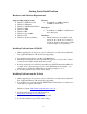
Getting Started with ProScan Hardware and Software Requirements Supported Operating Systems Windows XP Professional Windows XP Home Windows XP Tablet PC Edition Windows 2000 Windows ME Windows Server 2003 Windows NT Windows 98 Second Edition Memory A minimum of 64MB of RAM (128MB recommended) Disk Space A minimum of 10MB of available hard drive disk space Hardware The PC must have an available 9-pin serial port.
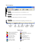
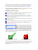
The User Interface Toolbar The toolbar provides single-click access to all of ProScan’s tools. Menu Bar The menu bar provides categorized access to all of ProScan’s functionality. Title Bar The title bar displays the name of the active tool selection. Status Bar The status bar displays useful information regarding your ProScan session.
Registering ProScan The ProScan software can be freely downloaded and installed from our web site, but the diagnostic and analysis tools cannot be used on a vehicle until the software has been purchased and registered. When you purchase ProScan you will be issued a serial number that will unlock the software and provide full functionality. Registering ProScan is a simple, one-time-only process that will take only a few seconds the first time you try connecting to a vehicle.
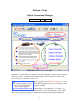
ProScan’s Tools Vehicle Connection Manager Toolbar Icon: Image 2: Vehicle Connection Manager Each time you run ProScan, the Vehicle Connection Manager is displayed automatically. This tool is used to establish communication with a vehicle, which is a required step before using any of ProScan’s other tools. TIP You should regularly visit our web site for important news and software upgrades. http://www.MyScanTool.
which is made conveniently accessible by means of the Manage Profiles button (Blue Circle, Image 2). Once you have defined a profile for the vehicle, you can make it the active vehicle profile by selecting it from the drop-down list (Blue Circle, Image 2). Step-by-step instructions for establishing communication with a vehicle are conveniently displayed on the left half of the window (Orange Circle, Image 2).
Vehicle Status Monitor Toolbar Icon: Image 5: Vehicle Status Monitor Your vehicle’s diagnostic system routinely performs system readiness tests. If your vehicle is in good operating condition, all tests supported by your vehicle should complete successfully. The Vehicle Status Monitor allows you to view the results of these tests along with some other important information.
Continuous Tests The Continuous Tests section displays whether or not your vehicle supports each continuous test, and if it does, whether or not the test has been successfully completed. Misfire Monitoring Misfire monitoring shall be supported on both spark ignition and compression vehicles if the vehicle utilizes a misfire monitor. Misfire monitoring shall always indicate complete for spark ignition engines.
5. Closed Loop – Fault with at least one oxygen sensor. May be using single oxygen sensor for fuel control. NOTE: Fuel systems do not normally refer to injector banks. Fuel systems are intended to represent completely different fuel systems that can independently enter and exit closed loop fuel. Banks of injectors on a V-engine are generally not independent and share the same closed-loop enablement criteria.
Diagnostic Trouble Codes Toolbar Icon: Image 6: Diagnostic Trouble Codes When your vehicle's malfunction indicator lamp (MIL) comes on, your vehicle has stored a code that identifies the problem detected. This code is known as a diagnostic trouble code (DTC). Diagnostic trouble codes are alphanumeric codes that are used to identify a problem that is present on any of the systems that are monitored by the onboard diagnostic system.
Pending and Stored Trouble Codes Explained When a problem is first detected, its corresponding DTC is typically recorded as a pending trouble code. Pending trouble codes do not illuminate the MIL on the dash, so the driver is not made aware of any potential problem at this time. If the vehicle’s diagnostic system continues to detect the same problem after multiple driving cycles, the DTC will become a stored code and the MIL will illuminate.
Freeze Frame Data Toolbar Icon: Image 7: Freeze Frame Data If your vehicle’s malfunction indicator lamp is illuminated, there could be freeze frame data stored in memory for one or more diagnostic trouble codes. Freeze frame data represent the value of multiple critical sensors at the time a problem is detected and a DTC is stored. This information allows technicians to determine how the vehicle was being driven when the problem occurred.
Oxygen Sensor Tests Toolbar Icon: Image 8: Oxygen Sensor Tests Oxygen sensors provide feedback to the vehicle’s computer estimating the air to fuel ratio so that fueling changes can be made to achieve peak engine performance and clean emissions. Therefore, oxygen sensors are arguably the most important sensors on modern fuel-injected vehicles. Most OBD-II vehicles perform tests on the oxygen sensors at least once per driving cycle.
To view test results for a specific oxygen sensor, select it from the drop-down list and click the “Read” button. The progress indicator at the bottom of the window will display the progress of the operation. If the test is supported and has been completed, the results will display in the table. The graphic at the bottom of the window represents a typical oxygen sensor output voltage waveform. The Test IDs are labeled in the graphic to help you visualize what each test result represents.
Live Sensor Grid Toolbar Icon: Image 9: Live Sensor Grid The Live Sensor Grid tool (Image 9) allows you to monitor a custom set of sensors in real-time. A powerful feature of this tool is its ability to record and playback sensor readings. This allows you to specify which sensors to monitor, go for a drive, and then safely playback the sensor readings once you have parked.
Live Sensor Graphs Toolbar Icon: Image 10: Live Sensor Graphs The Live Sensor Graphs tool (Image 10) functions similarly to the Live Sensor Grid tool. However, the Live Sensor Graphs tool does not allow recording and is limited to displaying 4 graphs. Graphing Sensor Readings To graph up to four sensors in real-time, you will need to check the checkbox beside of each sensor you intend to use. Then select each sensor to graph, the units of measure, and the type of graph.
Race Track Analysis Toolbar Icon: Image 11: Race Track Analysis TIP Wheel-spin will lead to inaccurate results. The Race Track Analysis tool (Image 11) allows you to easily and accurately generate a ¼ mile timeslip. This tool is intended for off-road use only. TIP If the vehicle’s speedometer is not accurate, use a speedometer calibration factor in the vehicle’s profile.
Dynamometer Toolbar Icon: Image 12: Dynamometer TIP Wheel-spin will lead to inaccurate results. The Dynamometer tool (Image 12) allows you to easily estimate a vehicle’s horsepower and torque curves throughout a specific RPM band. Accuracy of the ProScan Dyno The most reliable way to dyno a vehicle is with the use of a chassis dynamometer. However, ProScan is able to estimate a vehicle's horsepower and torque curves based upon factors such as vehicle weight and acceleration.
Tips for Best Results with the ProScan Dyno Tool: You will need to be on a level road surface. If you are accelerating downhill, your vehicle will accelerate quicker than normal and ProScan will think your vehicle has more power than it truly does. If you accelerate uphill, ProScan will under-rate your vehicle's power. You will need to avoid wheel-spin. ProScan cannot determine when your vehicle is spinning its tires.
Diagnostic Report Generator Toolbar Icon: Image 13: Diagnostic Report Generator The Diagnostic Report Generator tool (Image 13) allows you to generate a single-page diagnostic report for a vehicle. Reports can be saved to disk for future viewing, or they can be printed out and provided to a client. All the text fields on the left half of the tool are optional, but are recommended if you operate a shop and want to present a professional-looking report.
Image 14: OBD-II Diagnostic Report At the top of the generated report display window (Image 14) are three buttons. The “Preview” button will display a common Print Preview dialog. The “Print” button will send the report to your printer. The “Save” button will present a common Save As dialog in which you can save the report to a file.
Terminal Toolbar Icon: Image 15: Terminal ProScan is an advanced graphical user interface for ELM-based OBD-II hardware. ProScan’s Terminal tool (Image 15) allows you to send custom hex-formatted requests directly to the ELM microprocessor housed within the OBD-II hardware interface. The Terminal should only be used by individuals who fully understand the OBD-II specification as defined in SAE J1979. For more information, see ELM Electronics at http://www.elmelectronics.com.
Communication Log Toolbar Icon: Image 16: Communication Log The Communication Log (Image 16) maintains a history of all requests sent to the vehicle and all responses received during a single ProScan session. This log is made viewable so that if any technical difficulties arise, you can provide a copy of the log along with customer support inquiries. The log should provide customer support representatives with sufficient information to quickly pinpoint the exact problem and provide assistance.
User Preferences Toolbar Icon: Image 17: User Preferences The User Preferences dialog allows you to save your company information. Storing your company information allows ProScan to automatically provide your details when needed. This eliminates a lot of repetitious typing.
Vehicle Profile Manager Toolbar Icon: Image 18: Vehicle Profile Manager The Vehicle Profile Manager allows you to create profiles for each vehicle you analyze with ProScan. A vehicle profile stores vehicle-specific information that ProScan may need during a session. The list box on the left of the dialog displays all vehicle profiles. Selecting a profile in the list will display its details on the right. To create a new profile, simply click the “New” button.
Transmission Specify if your vehicle has an automatic or manual transmission. Speedometer Calibration Factor The speedometer calibration factor allows ProScan to compensate for incorrect speedometer readings due to non-stock tire sizes. If your vehicle has larger or smaller tires than stock and your speedometer has not been calibrated, you need to specify a speedometer calibration factor so that ProScan can correct your speedometer readings.
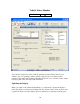
Communication Settings Toolbar Icon: Image 20: Communication Settings The Communication Settings dialog (Image 20) is where you configure the ProScan software to work with your ELM-based OBD-II interface hardware. Serial Port The serial port setting defines which physical serial port on your PC has the OBD-II interface hardware connected to it. If using a USB-to-Serial adapter, you will need to specify the serial port being emulated by the USB-to-Serial driver.
Diagnostic Trouble Code Breakdown DTCs are composed of five characters; one letter followed by 4 digits. Example DTCs: Digit 1 = System Identifier Digit 1 P0134 P1155 B0042 C1132 U3201 System P Powertrain B Body C Chassis U Undefined Digit 3 = Sub-System Digit 2 = Type of Code Definition Digit 3 Generic: Same definition for all manufacturers. Manufacturer-Specific: Definition varies among manufacturers.
Oxygen Sensor and Catalyst Configuration Examples 32
Troubleshooting If you can’t establish a working connection with your vehicle, try the following troubleshooting procedures. 1. Do you have the latest ProScan software installed on your PC? Yes: No: Continue to the next step. See the “Getting Started” section of this manual. 2. Are you able to launch the ProScan software? Yes: No: Continue to the next step. Make sure that your PC meets the minimum system requirements provided in the “Getting Started” section of this manual.
4. Is the OBD-II interface module receiving power from the vehicle as indicated by the LEDs? Yes: No: Continue to the next step. Make sure the OBD-II cable is securely attached from the vehicle’s 16pin diagnostic connector into the OBD-II interface module. Also make sure you have the vehicle’s ignition turned to the ON position, or go ahead and start the engine. 5. Have you edited ProScan’s communication settings to work properly with your hardware configuration? Yes: No: Continue to the next step.
9. Are you receiving an error stating that the OBD-II interface module could not be detected? Yes: Make sure that you have selected the correct serial port under ProScan’s Communication Settings dialog. Make sure that the interface is receiving power as indicated by its LEDs. Make sure that the cables and interface are securely fastened between the vehicle and your PC. If you are using a USB-to-Serial adapter, make sure that you have installed the drivers according to the manufacturer’s instructions.
12. Did the preceding troubleshooting process help you pinpoint and correct the problem you have been experiencing? Yes: No: Congratulations, you can begin using ProScan on your vehicle. We’re sorry that you are experiencing difficulties using ProScan on your vehicle. If you have access to another OBD-II vehicle, we recommend that you first try using ProScan on it. This could rule out the possibility of a problem with your OBD-II interface hardware.