
TXV Installation Instructions

A
TTENTION
I
NSTALLING
P
ERSONNEL
As a professional installer you have an obligation to know the
product better than the customer. This includes all safety
precautions and related items.
Prior to actual installation, thoroughly familiarize yourself with
this Instruction Manual. Pay special attention to all safety
warnings. Often during installation or repair it is possible to
place yourself in a position which is more hazardous than
when the unit is in operation.
Remember, it is your responsibility to install the product safely
and to know it well enough to be able to instruct a customer
in its safe use.
Safety is a matter of common sense...a matter of thinking
before acting. Most dealers have a list of specific good safety
practices...follow them.
The precautions listed in this Installation Manual are intended
as supplemental to existing practices. However, if there is a
direct conflict between existing practices and the content of
this manual, the precautions listed here take precedence.
HIGH VOLTAGE !
D
ISCONNECT
ALL
POWER
BEFORE
SERVICING
.
M
ULTIPLE
POWER
SOURCES
MAY
BE
PRESENT
. F
AILURE
TO
DO
SO
MAY
CAUSE
PROPERTY
DAMAGE
,
PERSONAL
INJURY
OR
DEATH
.
WARNING
EXPANSION VALVE KITS
INSTALLATION INSTRUCTIONS
S
HIPPING
I
NSPECTION
Upon receiving the product, inspect it for damage from ship-
ment. Shipping damage, and subsequent investigation is the
responsibility of the carrier. Verify the model number, speci-
fications, electrical characteristics, and accessories are cor-
rect prior to installation. The distributor or manufacturer will
not accept claims from dealers for transportation damage or
installation of incorrectly shipped units.
C
ODES
& R
EGULATIONS
This product is designed and manufactured to comply with
national codes. Installation in accordance with such codes
and/or prevailing local codes/regulations is the responsibil-
ity of the installer. The manufacturer assumes no responsi-
bility for equipment installed in violation of any codes or regu-
lations.
P
RE
-I
NSTALLATION
I
NSTRUCTIONS
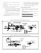
IMPORTANT: Piston must be removed from the Flowrator
Distributor Assembly for proper Expansion Valve operation.
Piston Removal:
1. Loosen the 13/16 nut 1 TURN ONLY to allow high
pressure tracer gas to escape. No gas indicates a
possible leak.
2. After the gas has escaped, remove the nut and discard
the cap, which may be black, clear or a brass cap.
3. Remove the check piston and seal and discard.
• Products
• Warranties
• Customer Services
IO-630G
12/2013
NOTE: SPECIFICATIONS AND PERFORMANCE DATA LISTED HEREIN ARE SUBJECT TO CHANGE WITHOUT NOTICE
Quality Makes the Difference!
All of our systems are designed and manufactured with the same high quality standards regardless of size or
efficiency. We have designed these units to significantly reduce the most frequent causes of product failure.
They are simple to service and forgiving to operate. We use quality materials and components. Finally, every
unit is run tested before it leaves the factory. That’s why we know. . .There’s No Better Quality.
Visit our website at www.daikincomfort.com, www.goodmanmfg.com or www.amana-hac.com for information on:
© 2004, 2006, 2009-2010, 2012-2013 Goodman Manufacturing Company, L.P.
is a registered trademark of Maytag Corporation or its related companies
and is used under license. All rights reserved.
• Parts
• Contractor Programs and Training
• Financing Options