
SPK Installation Instructions

3
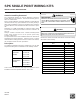
16. Place the cover on the kit as shown in Figure 4. Drive the
cutting screw provided with the single point kit to attach the
cover using the hole shown in Figure 4. Once the hole is
made, remove the cutting screw and replace with the blunt tip
screw also provided with the kit.
NOTE: Breaker for single point kit must be in the OFF position,
for the cover to fit correctly.
Single
Point
Breaker
Use
Cutting Screw
to attach
kit cover.
Figure 4
17. Flip single point breaker to the ON position.
18. Attach wiring diagram label next to the unit wiring diagram that
is located on the back of the control box door.
19. Attach blower compartment and control box door back on the
unit.
20. Begin the normal unit start-up procedures.
Multi-Position Models
1. Disconnect all power to the unit.
WARNING
HIGH VOLTAGE!
DISCONNECT ALL POWER BEFORE SERVICING OR INSTALLING
THIS UNIT.
MULTIPLE POWER SOURCES MAY BE PRESENT. FAILURE
TO DO SO MAY CAUSE PROPERTY DAMAGE, PERSONAL INJURY OR
DEATH.
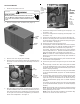
2. Remove the control box and blower door. See Figure 5.
Control
Box
Door
Blower
Door
Figure 5
3. Remove cover from single point assembly.
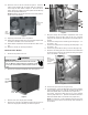
4. Remove the 2 screws in the blower housing and use these to
mount the single point assembly as shown in Figure 6.
Figure 6
5. Bring line voltage into the blower compartment. Use one of
the knockouts at the top right corner of the unit. Instead of
going into the control box, bring power to the single point as-
sembly.
6. Connect line voltage to the middle lug (for heat pumps – L1 /
for coolers – L2).
7. Connect line voltage to the far right lug (for heat pumps – L2 /
for coolers – L1).
8. Connect the ground wire to the lug on the far left (Figure 6).
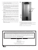
9. Route the unit wiring (the wires connected to the breaker and
the shorter green wire) into the control box through the grom-
met on the bottom. See Figure 7.
Bring
unit harness
to control box
through
grommet here.
Figure 7
10. Connect the green wire into the ground lug.
11. For heat pumps, connect the black wires to L1 on the contactor,
and the purple wires to L2. (SPK-50 and SPK-60 will have a
black wire labeled with a #3 instead of the purple wire.)
For coolers, connect the black wires to L2 on the contactor
and the purple wires to L1. (SPK-50 and SPK-60 will have a
black wire labeled with a #3 instead of the purple wire.)
NOTE: If needed the 2 male multiplier terminals that come
with the kit can be used to create enough open terminals on
the contactor.