
Specifications

2
INSTALLATION
The outdoor thermostat is designed to be installed in the space
allocated in the control box of the Amana
®
and Goodman cool-
ing and heat pump units.
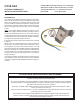
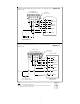
Set Point
A
djustment
Screw
Set Point
Indicator
Mark
(Shown @ Oº F)
The rmostat
Dial
DEAD
DIAL
315º
45º
COLD
(Turn Clockwise)
WARM (Turn Counterclockwise)
OT18-60
THERMOSTAT CAM
Figure 1
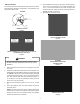
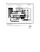
Normally Open
Contacts 2-1
Close On
Temperature Fall
Normally Closed
Contacts 2-3
Open On
Temperature Fall
RANCO THERMOSTAT - RANCO PART # A22-1260-00
GOODMAN PART # B13708-67
Figure 2
WARNING
T
O AVOID PERSONAL INJURY OR DEATH DUE TO ELECTRICAL SHOCK,
DISCONNECT ELECTRICAL POWER BEFORE INSTALLING THE OUTDOOR
THERMOSTAT.
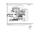
1. Remove the sheet metal screws securing the unit control
box cover.
2. Install the OT18-60A Outside Thermostat using the sup-
plied bracket and self-drilling screws (see Figures 3 through
9.). NOTE: Early Amana
®
and Goodman split, packaged
cooling and heat pump units, refer to Figures 3 through 6.
AS*, GS* and SS* split cooling and heat pump units, re-
fer to Figures 7 and 8. GP* packaged cooling and heat
pump units, refer to Figure 9.)
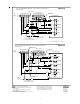
3. Wire the thermostat per Figures 10, 11, 12, 13, 14, and
15.
4. Route the capillary away from live terminals to prevent
electrical shorts.
NOTE: Outdoor Thermostat copper capillary will remain
inside of the control box on early Amana® and Goodman
models. On AS*,GS*, GP* and SS* models, the capillary
will extend outside the control box.
5. Set installed thermostat(s) to the proper outdoor temper-
ature. Insert a screwdriver in slot of thermostat dial (Fig-
ure 1). Turn set point indicator as shown in figure to de-
sired temperature setting on label (counterclockwise for
WARM, clockwise for COLD).
6. Reinstall the control box cover.
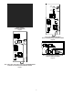
GOODMAN
SPLIT SYSTEM HEAT PUMP
Figure 3
GOODMAN
PACKAGE SYSTEM COOLING
AND HEAT PUMP
Figure 4
AMANA
®
BRAND
REMOTE HEAT PUMP
Figure 5