
Specifications

OT18-60A
OUTDOOR THERMOSTAT
INSTALLATION INSTRUCTIONS
Goodman Manufacturing Company, L.P. © 2003-2006
2550 North Loop West, Suite 400, Houston, TX 77092
www.goodmanmfg.com -or- www.amana-hac.com
P/N: IO-510D Date: March 2006
ATTENTION INSTALLING PERSONNEL
As a professional installer you have an obligation to know the product better than the customer. This
includes all safety precautions and related items.
Prior to actual installation, thoroughly familiarize yourself with this Instruction Manual. Pay special attention
to all safety warnings. Often during installation or repair it is possible to place yourself in a position which is
more hazardous than when the unit is in operation.
Remember, it is your responsibility to install the product safely and to know it well enough to be able to
instruct a customer in its safe use.
Safety is a matter of common sense...a matter of thinking before acting. Most dealers have a list of specific
good safety practices...follow them.
The precautions listed in this Installation Manual are intended as supplemental to existing practices.
However, if there is a direct conflict between existing practices and the content of this manual, the
precautions listed here take precedence.
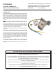
DESCRIPTION
This single pole double throw thermostat device with adjust-
able 0° to 45° temperature range is employed in conjunction
with the room thermostat to control the electric heaters that
have been added to Goodman and Amana
®
cooling and heat
pump product. This kit includes an Outdoor Thermostat, three
wires, mounting bracket, (3) wire caps, and (2) self-drilling
screws.
Note: If the outdoor ambient temperature is below 0° F (-18°
C) with 50% or higher Relative Humidity, an Outdoor Thermo-
stat must be installed and set at (0º F) on the dial. Failure to
comply wth this requirement may result in damage to the prod-
uct which may not be covered by the manufacturer’s warranty.
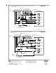
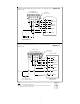
See Figures 12 and 15 for wiring connections.
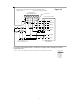
The schematic and the terminal view of this device is showed
in Figure 2:
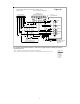
When used as an outdoor thermostat to control increments of
electric heat, connections will be made to terminals 2 and 1.
As temperature rises above the set point contacts 2 to 1 will
open thus preventing the controlled increment of supplemental
heat from operating. As outdoor temperature falls below the
set point contacts 2 to 1 will close allowing the controlled in-
crement of heat to operate. See Figures 10, 11, 13, and 14 for
wiring connections.
Use the wires supplied for Outdoor Thermostat connections. If
the installation is with an All Fuel kit, refer to the Installation
Instructions supplied with the AFE18 All Fuel kit for wiring con-
nections.