
OT18-60 Installation Instructions

7
R
W2 C RYO W1G E
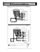
TYPICAL H/P
ROOM THERMOSTAT
12
PACKAGE HEAT PUMP
LOW VOLTAGE
JUNCTION BOX
BLUE
BROWN
WHITE
ORANGE
GREEN
YELLOW
RED
#18 GAUGE 8 WIRE
R
Y
G
O
O
Y
G
R
BL
BL
BR
W
BR
W
3
BL
Y
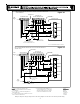
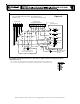
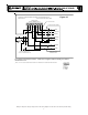
PACKAGE SYSTEM WIRING DIAGRAM - HEAT PUMPS ONLY!
ABOVE 10 kW
Figure 15
For outdoor temperatures below 0° F with 50% or higher relative humidity,set outdoor
thermostat at 0° F
.
NOTE 1: OT18 #2 CAN BE CONNECTED BETWEEN W2 OF THERMOSTAT AND BROWN WIRE IF DESIRED.
TWO-STAGE ELECTRIC HEAT
COLOR CODES
R --RED
Y --YELLOW
BR-BROWN
O --ORANGE
W -WHITE
G --GREEN
BL-BLUE
OUTDOOR THERMOSTAT #1
CLOSE ON TEMPERATURE FALL
BL
12
OUTDOOR THERMOSTAT #2
(IF USED, SEE NOTE 1)
Wiring is subject to change. Always refer to the wiring diagram on the unit for the most up-to-date wiring.