
OT18-60 Installation Instructions

2
1. Remove the sheet metal screws securing the unit control
box cover.
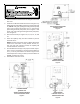
2. Install the OT18-60A Outside Thermostat using the sup-
plied bracket and self-drilling screws (see Figures 3 through
9.). NOTE: Early split, packaged cooling and heat pump
units, refer to Figures 3 through 6. AS*, D*, GS* and SS*
split cooling and heat pump units, refer to Figures 7 and
8. AP*, GP*, DP* packaged cooling and heat pump units,
refer to Figure 9.
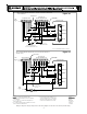
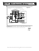
3. Wire the thermostat per Figures 10, 11, 12, 13, 14, and
15.
4. Route the capillary away from live terminals to prevent
electrical shorts.
NOTE: Outdoor Thermostat copper capillary will remain
inside of the control box on early models. On AS*, D*,
GS*, SS*, AP*, GP* and DP* models, the capillary will
extend outside the control box.
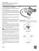
5. Set installed thermostat(s) to the proper outdoor temper-
ature. Insert a screwdriver in slot of thermostat dial (Fig-
ure 1). Turn set point indicator as shown in figure to de-
sired temperature setting on label (counterclockwise for
WARM, clockwise for COLD).
6. Reinstall the control box cover.
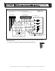
GOODMAN
®
BRAND
DAIKIN D***SN
AMANA
®
BRAND AN* MODELS
SPLIT SYSTEM HEAT PUMP
Figure 3
EARLY
PACKAGE SYSTEM COOLING
AND HEAT PUMP
Figure 4
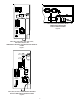
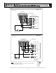
AMANA
®
BRAND
REMOTE HEAT PUMP
Figure 5
AMANA
®
BRAND
DAIKIN D***SA, D***TC
REMOTE HEAT PUMP
Figure 6