
All Fuel Kit Install Instructions

AFE18-60A
Goodman Manufacturing Company, L.P. © 2004 - 2008
5151 San Felipe, Suite 500, Houston, TX 77056
www.goodmanmfg.com
P/N: IO-627A Date: October 2008
ATTENTION INSTALLING PERSONNEL
As a professional installer you have an obligation to know the product better than the customer. This
includes all safety precautions and related items.
Prior to actual installation, thoroughly familiarize yourself with this Instruction Manual. Pay special
attention to all safety warnings. Often during installation or repair it is possible to place yourself in a
position which is more hazardous than when the unit is in operation.
Remember, it is your responsibility to install the product safely and to know it well enough to be able to
instruct a customer in its safe use.
Safety is a matter of common sense...a matter of thinking before acting. Most dealers have a list of
specific good safety practices...follow them.
The precautions listed in this Installation Manual are intended as supplemental to existing practices.
However, if there is a direct conflict between existing practices and the content of this manual, the
precautions listed here take precedence.
DESCRIPTION
The AFE18 control is designed for use in heat pump
applications where the indoor coil is located above/down-
stream of a gas or fossil fuel furnace. It will operate with
single and two stage heat pumps and single and two stage
furnaces. The AFE18 control will turn the heat pump unit off
when the furnace is turned on. An anti-short cycle feature
is also incorporated which initiates a 3 minute timed off
delay when the compressor goes off. On initial power up or
loss and restoration of power, this 3 minute timed off delay
will be initiated. The compressor won’t be allowed to restart
until the 3 minute off delay has expired. Also included is a
5 second de-bounce feature on the “Y, E, W1 and O”
thermostat inputs. These thermostat inputs must be present
for 5 seconds before the AFE18 control will respond to it.
An optional outdoor thermostat, OT18-60A, can be used
with the AFE18 to switch from heat pump operation to
furnace operation below a specific ambient temperature
setting, i.e. break even temperature during heating. When
used in this manner, the “Y” heat demand is switched to the
“W1” input to the furnace by the outdoor thermostat and the
furnace is used to satisfy the first stage “Y” heat demand.
On some controls, if the outdoor thermostat fails closed in
this position during the heating season, it will turn on the
furnace during the cooling season on a “Y” cooling demand.
In this situation, the furnace produces heat and increases
the indoor temperature thereby never satisfying the cooling
demand. The furnace will continue to operate and can only
be stopped by switching the thermostat to the off position or
removing power to the unit and then replacing the outdoor
thermostat. When the AFE18 receives a “Y” and “O”
input from the indoor thermostat, it recognizes this as a
cooling demand in the cooling mode. If the outdoor thermo-
stat is stuck in the closed position switching the “Y” demand
to the “W1” furnace input during the cooling mode as
described above, the AFE18 won’t allow the furnace to
operate. The outdoor thermostat will have to be replaced
to restore the unit to normal operation.
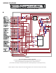
AFE18-60A INSTALLATION
The AFE18-60A should be installed on the side of the
furnace close to the 24Vac controls wires for field connec-
tions. The system must be connected in accordance with
the wiring diagram supplied with the AFE18 control and
shown in these instructions. Standard thermostat cables
can be used for wiring connections between the thermostat
and heat pump unit. See Fig. 1.
ALL FUEL SYSTEM CONTROL BOARD
INSTALLATION INSTRUCTIONS