
Installation Instructions

4
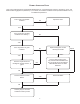
WIRING DIAGRAM
PRESSURE SWITCH
MASONRY VENT KIT LIMIT
YL
RD
BK
YL
C
NO
WIRING DIAGRAM
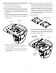
6. Position the masonry vent kit body to the bottom plate and
secure using the (2) screws supplied with the vent kit. The
safety limit must be on the right side when facing the fur-
nace. Ensure the flue pipe inside the masonry vent kit fits
over the furnace flue top.
Safety Limit
Masonry Vent
Kit Body
7. Connect the 5” diameter field installed type-B double wall
flue pipe to the masonry vent kit body and secure on three
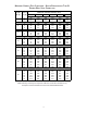
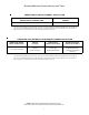
sides using field supplied screws. Refer to the Masonry
Chimney Flue Capacity table on page 6.
8. Masonry Vent Kit Wiring
a. Locate the 2-wire wiring harness included with the ma-
sonry vent kit.
b. Locate the wiring harness end with (2) female 1/4”
quick connect terminals. Connect these terminals to
the safety limit on the masonry vent kit body.
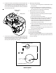
9. Masonry Vent Kit to Furnace Wiring
a. Remove the furnace access panel.
b. Route the masonry vent kit wiring harness through a
louver in the furnace top.
c. Locate the furnace pressure switch.
d. Using needle nose pliers, disconnect the yellow wire
from the pressure switch’s common (C) terminal.
Connect the vent kit wiring harness wire with a 1/4”
male quick connect terminal to the yellow wire re-
moved from the pressure switch.
e. Connect the vent kit wiring harness wire with a 1/4” fe-
male quick connect terminal to the pressure switch’s
common (C) terminal.
f. Review the wiring diagram on page 4 and verify the ma-
sonry vent kit to furnace wiring.
10. Reinstall the access panel.
11. Turn on the gas supply.
12. Turn on the electrical supply.
13. Using the room thermostat, place the unit into operation.
Observe (3) ignition cycles and verify that the furnace func-
tions as expected.