
Installation Instructions

3
MASONRY VENT KIT INSTALLATION INSTRUCTIONS
1. Turn off the gas supply to the furnace.
2. Turn off the electrical power to the furnace.
3. Remove the furnace control access panel.
NOTE: For new installations the flue top has not been installed
on the furnace. The flue top must be removed from its
shipping location on burner manifold and placed on the
flue transition. Screws for the flue top are located in the
literature pack.
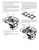
4. Remove the (4) screws securing the furnace flue top to the
furnace flue transition using a 1/4” nut driver. Retain the
screws for later use. The flue top must remain in place on
the flue transition.
Screws
Flue Top
5. Masonry Vent to Furnace Connection
a. Locate the masonry vent bottom plate supplied with
the masonry vent kit.
b. Orient the masonry vent bottom plate over the furnace
flue top. A label on the bottom plate indicates the cor-
rect orientation.
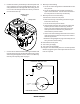
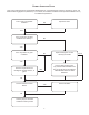
NOTE: MVK-02 bottom plate includes a keying tab. Fur-
nace models for which the MVK-02 is approved has a
keying slot in the furnace top. The keying tab on the
MVK-02 fits into the keying slot in the furnace top on
applicable furnace models. Verify that the masonry vent
kit model is applicable to your furnace model prior to
installation. If your furnace model is correct for the MVK-
02 and the keying slot is not present on the furnace top,
furnace top 0121F00463DG must be purchased. See
the bottom plate figure below.
MVK-01 Bottom Plate
MVK-02 Bottom Plate
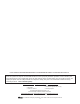
c. Secure the bottom plate to the furnace flue transition
using the screws removed in step 4 (or, in the case of a
new installation, the screws from the literature pack).
The furnace flue top must protrude through the hole in
the masonry vent bottom plate.
Orientation
Label
Screws
Flue Top
Masonry Vent
Bottom Plate