
MBR Installation Manual


5
LOW VOLTAGE WIRING
Low voltage wiring connections are made at the top of the cabi-
net. See the “Thermostat Wiring” section of this manual for
typical low voltage wiring connections. A minimum 18 AWG
wire must be used for installations up to 50 feet and 16 AWG
wire for installations over 50 feet.
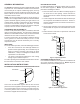
MISCELLANEOUS ELECTRICAL
The unit transformer is factory connected for 240 V operation.
If unit is to operate on 208 V, disconnect the red wires from
terminal 3 of the unit transformer and connect them to terminal
2 of the unit transformer.
INSTALLER: It is important to follow these instructions when
installing the MB series of air handlers.
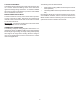
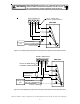
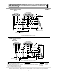
THERMOSTAT CONNECTIONS
The following composite wiring diagrams detail various con-
figurations in which your MB air handler can be used. Examples
include single stage cooling, two stage cooling and heat pump
with single or two stage electric heating. All these configura-
tions can be applied with convenient connections to outdoor
thermostat applications.
The following sections will be detailed:
• Single Stage Cooling (GMC Thermostat part # CHT18-
60 or equivalent)
• Heat Pump (GMC Thermostat part #HPT18-60 or equiva-
lent)
Each diagram details the connections between room thermo-
stat and MB air handlers, and the connections between the
MB air handlers and the Condensing Unit (or Heat Pump) with
optional connections to Outdoor Thermostats.