
MBR Installation Manual


4
NOTE: Supply ductwork for counterflow applications, must be
Class I. However, if combustible ductwork is used, sheet metal
protection is required.
1. Place the blower and coil cabinet assembly supply outlet
on the supply duct or duct opening. Ensure there is ample
support for the unit and all attached ductwork.
2. Connect refrigerant and condensate drain connections per
the evaporator coil installation instructions. Ensure re-
frigerant and drain lines do not interfere with service ac-
cess to the unit.
3. Attach return ductwork. Seal connections between unit
and ductwork as required to reduce/eliminate air leak-
age.
4. Make electrical connections as specified in “Electrical”
section of this manual.
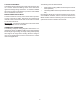
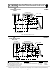
HORIZONTAL INSTALLATION
For horizontal installations, the coil cabinet must be upstream
of the blower cabinet (Figures 5 and 6). NOTE: All panels
should be in place when installing the unit.
1. Set the unit near its final installation place. The unit must
be supported along the entire length of the unit. Rubber
isolation pads may be used to reduce sound and vibration
transmission. Ensure there is ample support for the unit
and all attached ductwork.
Air Flow
Blower Cabinet
Support
FIGURE 5 - Attic Installation
Air Flow
Rods
Support
FIGURE 6 - Hanging Installation
2. If installed above a finished ceiling or living space, be sure
to put a secondary drain pan under the entire unit, and
pipe the drain separately from the main condensate drain.
3. Connect refrigerant and condensate drain connections per
the coil section installation instructions. Ensure refriger-
ant and drain lines do not interfere with service access to
the unit.
4. Attach return and supply ductwork. Seal connections.
5. Make electrical connections as specified in “Electrical”
section of this manual.
ELECTRICAL CONNECTIONS
Consult the local power company and local codes before in-
stalling this unit. All wiring must be in accordance with the
National Electrical Code as well as all local codes. Knockouts
have been provided on side and top of the cabinet for the instal-
lation of the electrical conduit. If the knockouts on the cabinet
sides are used for electrical conduit, an adapter ring must be
used in order to meet UL1995 safety requirements. Use Mini-
mum Circuit Ampacity and type of wire to determine proper
wire size. The unit MUST be properly grounded. A ground lug
is provided in the unit.
Check all factory connections before connecting electrical power
to unit to ensure none were loosened or disconnected during
shipping and handling.
TO PREVENT PERSONAL INJURY OR DEATH DUE TO ELECTRICAL SHOCK,
DISCONNECT THE ELECTRICAL POWER BEFORE ELECTRICALLY CONNECTING
THE UNIT.
TO AVOID THE RISK OF PROPERTY DAMAGE, PERSONAL INJURY OR FIRE
USE ONLY COPPER CONDUCTORS.
TO AVOID THE RISK OF PERSONAL INJURY, WIRING TO THE UNIT MUST BE
PROPERLY POLARIZED AND GROUNDED.
CAUTION
ALL WIRING MUST COMPLY WITH APPLICABLE LOCAL AND NATIONAL CODES.
TYPE AND LOCATION OF FUSED DISCONNECT SWITCH(ES) MUST COMPLY
WITH ALL APPLICABLE CODES AND PROVIDE OVERCURRENT PROTECTION AS
SHOWN ON THE NAMEPLATE.
WARNING
HIGH VOLTAGE WIRING
If heater kits will not be installed, remove the proper size knock-
out for the electrical conduit connection. Connect electrical
conduit to the unit using two washers to make an approved
connection.
The power supply wires must be connected to the red and
black power wiring. Two wire nuts are provided in the bag
assembly for this connection. Wrap the wire nuts with electri-
cal tape. (Insulated crimp type connectors, field supplied, may
be substituted for the wire nuts and electrical tape provided
proper size connectors are used.) A ground wire MUST be
connected to the ground lug inside the unit.