
Installation Instructions

7
HIGH VOLTAGE!
DISCONNECT ALL POWER BEFORE SERVICING.
MULTIPLE POWER SOURCES MAY BE PRESENT. FAILURE TO DO SO
MAY CAUSE PROPERTY DAMAGE, PERSONAL INJURY OR DEATH.
WARNING
ROOM THERMOSTAT
WY
G
R
#18 GA. 4 WIRES WITH
COOLING 3 WIRES WITHOUT
R
G
W
Y
TO CONDENSING
UNIT 24V. CONN ECT IONS
#18 GA. 2 WIRES
BLUE
WHITE
GREEN
RED
CONTACTOR
COIL
MBR UNIT
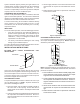
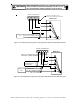
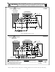
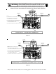
Figure 7- Low Voltage Wiring Diagram for Cooling Unit with optional heat kit 10KW and below
W2
W
YGR
R
G
Y
W
GREEN
RED
WHITE
BLUE
BROWN
#18 GA. 4 WIRE WITH
COOLING 3 WIRE WITHOUT
ROOM THERMOSTAT
OUTDOOR
THERMOSTAT
(OPTIONAL)
CONDENSING
UNIT 24V. CONNECTIONS
#18 GA. 2 WIRES
#18 GA. 2 WIRES
CONTACTOR
COIL
MBR UNIT
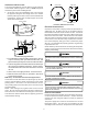
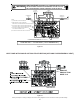
Figure 8 - Low Voltage Wiring Diagram for Cooling Unit with optional heat kit 15KW and above
Wiring is subject to change, always refer to the wiring diagram on the unit for the most up-to-date wiring.