
Installation Instructions

5
cal tape. (Insulated crimp type connectors, field supplied, may
be substituted for the wire nuts and electrical tape provided
proper size connectors are used.) A ground wire MUST be
connected to the ground lug inside the unit.
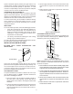
LOW VOLTAGE WIRING
Low voltage wiring connections are made at the top of the cabi-
net. See the “Thermostat Wiring” section of this manual for
typical low voltage wiring connections. A minimum 18 AWG
wire must be used for installations up to 50 feet and 16 AWG
wire for installations over 50 feet.
MISCELLANEOUS ELECTRICAL
The unit transformer is factory connected for 240 V operation.
If unit is to operate on 208 V, disconnect the red wires from
terminal 3 of the unit transformer and connect them to terminal
2 of the unit transformer.
INSTALLER: It is important to follow these instructions when
installing the MB series of air handlers.
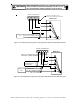
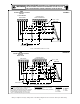
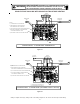
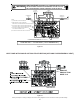
THERMOSTAT CONNECTIONS
The following composite wiring diagrams detail various con-
figurations in which your MB air handler can be used. Examples
include single stage cooling, two stage cooling and heat pump
with single or two stage electric heating. All these configura-
tions can be applied with convenient connections to outdoor
thermostat applications.
The following sections will be detailed:
• Single Stage Cooling (GMC Thermostat part # CHT18-
60 or equivalent)
• Heat Pump (GMC Thermostat part #HPT18-60 or equiva-
lent)
• Two Stage Cooling with Conventional Two Stage Ther-
mostat (GMC Thermostat part #CHT90-120 or equiva-
lent)
• Two Stage Cooling with Conventional Two Stage Ther-
mostat (Encoded with Add-on Diodes)
• Two Stage Encoded Thermostat from Goodman Manu-
facturing Part #CHET18-60
Each diagram details the connections between room thermo-
stat and MB air handlers, and the connections between the
MB air handlers and the Condensing Unit (or Heat Pump) with
optional connections to Outdoor Thermostats. For each con-
figuration,
refer to the explanation of the proper jumper(s) to remove for
the corresponding blower speed that will result in the pro-
grammed ECM
TM
motor on MBE units.
Important: When matching the MBE air handlers to a single
stage cooling unit or heat pump, remember to connect the “Y/
Y2” thermostat connection on the Variable speed board (VSTB)
to the thermostat. Connecting “Y1” will result in first stage
cooling blower speed.
Note: The two stage configurations are illustrated to detail con-
nections to the two capacity condensing units and heat pumps.
An equivalent thermostat can be used in place of the Goodman
thermostat part number. The GMC thermostats listed are
mercury type.
When utilizing the encoded version of a conventional two stage
cooling and heating electronic thermostat (add-on diodes), a
hard wire “C” (common of 24V secondary voltage) must be
used. This encoded version will not work with a “power robbing”
thermostat (i.e. no common connection). One TSTWK01 kit
is required for the encoded applications on MBE units.
NOTE: When using a conventional two stage thermostat for cooling
or heat pump applications with a two stage compressor, dip switch
#4 must be set to the “OFF” position on MBE units.
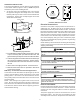
MBE MOTOR
This section references the operation characteristics of the
MBE model motor only. The ECM control board is factory set
with the dipswitch #4 in the “ON” position and all other
dipswitches are factory set in the “OFF” position. For most
applications, the settings are to be changed according to
the electric heat size and the outdoor unit selection.
The MBE product uses a General Electric ECM
TM
motor. This
motor provides many features not available on the traditional
PSC motor. These features include:
• Improved Efficiency
• Constant CFM
• Soft Start and Stop
• Improved Humidity Control
MOTOR SPEED ADJUSTMENT
Each ECM™ blower motor has been preprogrammed for op-
eration at 4 distinct airflow levels when operating in Cooling/
Heat Pump mode or Electric Heat mode. These 4 distinct
levels may also be adjusted slightly lower or higher if desired.
The adjustment between levels and the trim adjustments are
made by changing the dipswitch(s) either to an "OFF" or "ON"
position.
DIPSWITCH FUNCTIONS
The MBE air handler motor has an electronic control that con-
tains an eight (8) position dip switch. The function of these
dipswitches are shown in Table 1.
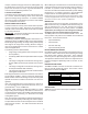
Dipswitch Number Function
1
2
3
N/A
4
Indoor Thermostat
5
6
7
8
Cooling & Heat Pump CFM
CFM Trim Adjust
Electric Heat
Table 1
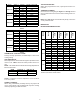
CFM DELIVERY
Tables 2 and 3 show the CFM output for dipswitch combina-
tions 1-2, and 5-6.