
Propane Conversion Kit Instructions

4
14. Replace the regulator adjustment screw and adjust it clock-
wise to bottom stop. Follow instructionsbelow beginning in
step 21 for checking & adjustment to verify manfold pres-
sure falls into the desired range.
15. Apply a liberal amount of pipe joint compound or pipe thread
tape to the threads and reassemble the piping previously
removed. Note: the pipe joint compound or pipe thread tape
must be resistant to L.P. gas.
16. Turn on the gas supply and check for leaks.
17. Turn on the electrical supply.
18. Adjust the room thermostat to allow for constant operation.
19. If you have the correct manifold pressure and the burn-
ers do not light, there may be air trapped in the lines.
Follow these instructions:
To check for air trapped in the supply line: Verify line
pressure is in the correct range. If manifold pressure is
indicated during the ignition trial, the valve is opening and
air may be in the line.
Units with hot surface ignitors: The valve will not open
until the ignitor is at the proper temperature (glowing
brightly).
Units with spark ignition: The valve will open as soon as
the spark starts. If no manifold pressure is indicated dur-
ing the trial for ignition, please return to step 13 to ensure
the correct spring was used and to ensure the regulator
adjustment is near the bottom of the adjustment range.
20. If gas inlet pressure falls outside the range of 11” and 13”
W.C. after the unit has been in operation for 15 minutes,
adjust the gas supply pressure (not manifold pressure),
check piping size, etc., and/or consult with local utility.
NOTE: Any other gas-fired equipment should be ON before
any adjustments are made.
21. Check manifold pressure. For propane gas, the manifold
pressure must be between 9.7” and 10.3” W.C.
22. Turn adjustment screw out (counterclockwise) to decrease
pressure, turn in (clockwise) to increase pressure. Only
small variations in gas flow should be made by means of
the pressure regulator adjustment. In no case should the
final manifold pressure vary more than plus or minus 0.3”
water column from the specified nominal pressure. Any
major changes in flow should be made by changing the
size of the burner orifices. The measured input rate to the
furnace must not exceed the rating specified on the unit
rating plate.
23. Reset all other appliances so they function normally.
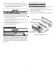
24. Turn off gas and electrical supply to the furnace, remove
the manometer hose from the pressure taps, and tighten
the inlet and outlet pressure tap screws using the 3/32”
Allen wrench (clockwise 7 in-lb minimum).
25. If regulator adjustment screw (removed in step 11) is white,
the gasket supplied with the kit must be installed on the
regulator cover screw. The gasket is not required if the
regulator adjustment screw is black.
26. Replace the regulator cover screw on the regulator sleeve.
27. Attach the kit provided WARNING label to the gas valve
where it can be readily seen. Also attach the small round
L.P. label to the top of the regulator cover screw.
28. Turn on the gas and electrical supply, energize the appli-
ance and recheck for leaks.
29. Observe at least 3 ignition cycles to assure quick and
smooth ignition and burner operation.
30. Reinstall the access panels.
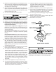
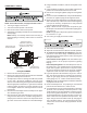
Regulator
Cover Screw
Plastic Regulator
Adjustment Screw
Regulator
Spring
Gasket (From
Conversion Kit)
Regulator
Sleeve
36G22 / 36J22 MODEL
Note: Conversion instructions for the Honeywell
VR8215 gas valve begin on the following page.