
Propane Conversion Kit Instructions

3
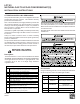
BEFORE BEGINNING CONVERSION:
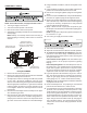
VALVE IDENTIFICATION
Before beginning conversion, the type valve you have must be
identified. Compare the gas valve presently on the equipment
to the drawing below to identify the correct valve you are
working with. Page numbers for the instructions for that valve
are below each drawing.
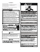
INLET
Inlet Pressure
Pressure Regulator
Adjustment
(Under Cap Screw)
Gas Valve
On/Off
Selector
Switch
OUTLET
Ta p
Outlet Pressure
Ta p
White-Rodgers 36G22 / 36J22
Instructions for these valves start on page 3.
FLOW DIRECTION
Gas Valve
ON/OFF Selector
Outlet Pressure
Tap 1/8 NPT 3/16
Inlet Pressure Tap
1/8 NPT 3/16 Allen
Regulator Pressure
A
djustment (Under Cap
Screw), Turn Clockwise to
Increase Pressure, Turn
Honeywell VR8215
Instructions for this valve start on page 5.
WHITE-RODGERS 36G22 / 36J22
CONVERSION INSTRUCTIONS
NOTE: For low NOx models, see page 6 for NOx screens.
1. Turn off gas supply to the furnace.
2. Turn off the electrical power to the furnace.
3. Remove the furnace control access panel.
4. Separate the gas supply union and remove associated down-
stream piping.
NOTE: Always use a backup wrench when removing or
replacing piping to avoid any undue strains or rotation of
controls.
5. Remove the wires from the gas valve.
6. Remove the 4 sheet metal screws that fasten the manifold/
gas valve assembly to the burner box.
7. Visually inspect orifices for damage and drill size (marked
on face with a 55) before installation. Using the 7/16"
wrench, remove all existing natural gas orifices and replace
with the appropriate marked 55 L.P. gas orifices contained
in this kit. Tighten the orifices to prevent gas leaks, but do
not overtighten. Retain the natural gas orifices for future
reconversion.
8. Reinstall the manifold/gas valve assembly into the appli-
ance. Rewire the gas valve.
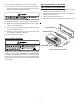
9. Using a 3/32” Allen wrench, loosen the inlet and outlet pres-
sure tap screw one (1) turn only (DO NOT REMOVE). At-
tach a length of 5/16” hose to each of the pressure taps.
Connect the 5/16” hose to two (2) separate manometers or
other adequate gauges having a scale range of at least 0”
to 15” of water column.
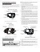
Pressure Regulator
Adjustment
(Under Cap Screw)
Gas Valve
On/Off
Selector
Switch
INLET
OUTLET
Inlet Pressure
Tap
Outlet Pressure
Ta p
White-Rodgers 36G22 / 36J22
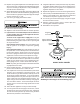
10. Using a flat blade screwdriver, remove the regulator cover
screw.
11. Using a flat blade screwdriver, remove plastic regulator ad-
justment screw located beneath the cover screw.
12. Remove the natural gas regulator spring from the regulator
sleeve.
13. Insert the kit (P/N B1880007, WR F92-0999) provided L.P.
regulator spring into the regulator sleeve.