
Installation Instructions

6
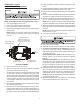
22. Turn adjustment screw out (counterclockwise) to decrease
pressure, turn in (clockwise) to increase pressure. Only
small variations in gas flow should be made by means of
the pressure regulator adjustment. In no case should the
final manifold pressure vary more than plus or minus 0.3”
water column from the specified nominal pressure. Any
major changes in flow should be made by changing the
size of the burner orifices. The measured input rate to the
furnace must not exceed the rating specified on the unit
rating plate.
23. Reset all other appliances so they function normally.
24. Turn off the gas and electrical supply to the appliance,
remove the pressure taps at the gas valve, reinstall the
plugs using pipe joint compound or tape.
25. Replace the regulator cover screw on the regulator sleeve.
26. Attach the kit provided ATTENTION label to the gas valve
where it can be readily seen.
27. Turn on the gas and electrical supply, energize the appli-
ance and recheck for leaks.
28. Observe at least 3 ignition cycles to assure quick and
smooth ignition and burner operation.
29. Reinstall the access panels.
NOx SCREEN REMOVAL
NOTE: To prevent premature heat exchanger failure, follow the
instructions in the NON-CONDENSING FURNACES AND
PACAKGE GAS-ELECTRIC section to remove all metal
screen inserts from the entrance of heat exchanger tubes
during propane conversions. Not all models will have metal
screen inserts.
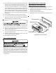
NON-CONDENSING FURNACES
AND PACKAGE GAS-ELECTRIC
1. Remove the screws securing the burner box to the parti-
tion panel. Separate burner box from unit.
2. Remove the screw(s) securing the NOx screen retention
plate and remove the plate.
3. Remove and discard NOx screens.
4. Reinstall the NOx screen retention plate and burner box.
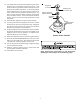
PARTITION PANEL
RETENTION PLATE
BURNER BOX ASSY.
SCREENS
Typical Nox Screen Removal