
Installation Instructions

3
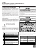
WHITE-RODGERS 36G22 / 36J22
CONVERSION INSTRUCTIONS
NOTE: For low NOx models, see page 6 for NOx screens.
1. Turn off gas supply to the furnace.
2. Turn off the electrical power to the furnace.
3. Remove the furnace control access panel.
4. Separate the gas supply union and remove associated down-
stream piping.
NOTE: Always use a backup wrench when removing or
replacing piping to avoid any undue strains or rotation of
controls.
5. Remove the wires from the gas valve.
6. Remove the 4 sheet metal screws that fasten the manifold/
gas valve assembly to the burner box.
7. Visually inspect orifices for damage and drill size (marked
on face with a 55) before installation. Using the 7/16"
wrench, remove all existing natural gas orifices and replace
with the appropriate marked 55 L.P. gas orifices contained
in this kit. Tighten the orifices to prevent gas leaks, but do
not overtighten. Retain the natural gas orifices for future
reconversion.
8. Reinstall the manifold/gas valve assembly into the appli-
ance. Rewire the gas valve.
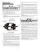
9. Using a 3/32” Allen wrench, loosen the inlet and outlet pres-
sure tap screw one (1) turn only (DO NOT REMOVE). At-
tach a length of 5/16” hose to each of the pressure taps.
Connect the 5/16” hose to two (2) separate manometers or
other adequate gauges having a scale range of at least 0”
to 15” of water column.
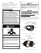
Pressure Regulator
Adjustment
(Under Cap Screw)
Gas Valve
On/Off
Selector
Switch
INLET
OUTLET
Inlet Pressure
Tap
Outlet Pressure
Ta p
White-Rodgers 36G22 / 36J22
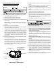
10. Using a flat blade screwdriver, remove the regulator cover
screw.
11. Using a flat blade screwdriver, remove plastic regulator ad-
justment screw located beneath the cover screw.
12. Remove the natural gas regulator spring from the regulator
sleeve.
13. Insert the kit (P/N B1880007, WR F92-0999) provided L.P.
regulator spring into the regulator sleeve.
14. Replace the regulator adjustment screw.
15. Apply a liberal amount of pipe joint compound or pipe thread
tape to the threads and reassemble the piping previously
removed. Note: the pipe joint compound or pipe thread tape
must be resistant to L.P. gas.
16. Turn on the gas supply and check for leaks.
17. Turn on the electrical supply.
18. Adjust the room thermostat to allow for constant operation.
19. If you have the correct manifold pressure and the burn-
ers do not light, there may be air trapped in the lines.
Follow these instructions:
To check for air trapped in the supply line: Verify line
pressure is in the correct range. If manifold pressure is
indicated during the ignition trial, the valve is opening and
air may be in the line.
Units with hot surface ignitors: The valve will not open
until the ignitor is at the proper temperature (glowing
brightly).
Units with spark ignition: The valve will open as soon as
the spark starts. If no manifold pressure is indicated dur-
ing the trial for ignition, please return to step 13 to ensure
the correct spring was used and to ensure the regulator
adjustment is near the bottom of the adjustment range.
20. If gas inlet pressure falls outside the range of 11” and 13”
W.C. after the unit has been in operation for 15 minutes,
adjust the gas supply pressure (not manifold pressure),
check piping size, etc., and/or consult with local utility.
NOTE: Any other gas-fired equipment should be ON before
any adjustments are made.
21. Check manifold pressure. For propane gas, the manifold
pressure must be between 9.5” and 10” W.C.