
Kit Instructions

3
WARNING
to prevent the possibiLity of gas Leaks, the pipe joint
compound must be resistant to L.p. gas.
17. Connect a calibrated water manometer (or appropriate
gas pressure gauge) at either the gas valve inlet pressure
boss or the gas piping drip leg. See gas valve gure for
location of inlet pressure boss.
NOTE: If measuring gas pressure at the drip leg or gas valve,
a eld-supplied hose barb tting must be installed prior to
making the hose connection.
18. Turn on the electrical supply.
19. Turn ON the gas supply and operate the furnace and all
other gas consuming appliances on the same gas supply
line.
Field Test Mode is intended to help a service person trou-
bleshoot and check out an installed appliance by quickly
bringing the furnace to high re.
To enter Field Test Mode the Fault Recall Push-Button
7. Remove the pressure switch hose connected to the gas
valve.
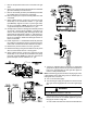
8. Remove the 4 sheet metal screws that fasten the manifold/
gas valve assembly to the burner box.
9. Remove the natural gas valve (0151M00024) and retain
for possible future reconversion to natural gas.
10. Remove old pipe joint compound and any debris from end
of manifold.
11. Apply a liberal amount of pipe joint compound or pipe
thread tape to the threads and install L. P. gas valve
(0151M00025). Tighten the valve to prevent gas leaks,
but do not overtighten. NOTE: the pipe joint compound
or pipe thread tape must be resistant to L.P. gas.
12. Visually inspect orices for damage and drill size (marked
on face with 1.25mm) before installation. Using the 7/16”
wrench, remove all existing #45 natural gas orices and
replace with the appropriate 1.25mm L.P. gas orices con-
tained in this kit. Tighten the orices to prevent gas leaks,
but do not overtighten. Retain the natural gas orices for
future reconversion.
13. Install completed L.P. manifold/valve assembly back into
the unit. Be sure to align the orices i n the burner opening.
Fasten with 4 sheet metal screws retained from Step 8.
14. Reattach the pressure switch hose to the gas valve.
15. Reattach the wiring to the gas valve and wire tie any loose
wires to avoid contact with hot or moving parts.
16. Apply a liberal amount of pipe joint compound or pipe
thread tape to the threads and reassemble the piping
previously removed. NOTE: the pipe joint compound or
pipe thread tape must be resistant to L.P. gas.