
Kit Instructions


4
WARNING
NEVER USE AN OPEN FLAME TO CHECK FOR GAS LEAKS.
WARNING
ATTACH THE WARNING LABEL PROVIDED IN THE KIT TO THE GAS
VALVE WHERE IT CAN BE READILY SEEN.
ATTACH THE SMALL, ROUND L.P. LABELS TO THE TOP OF THE
REGULATOR COVER SCREWS.
NOTE: for hybrid models, the control board dip switches
need to be set to 2 stg position to set and verify fi rst stage
heat. (See Installation Instructions supplied with the unit for
dip switch settings)
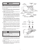
23. Using a soap and water solution, check for leaks around
the gas valve/manifold connection and the burner orifi ces.
Repair any leaks before continuing.
24. NOTE: Any other gas-fi red equipment should be ON
before any adjustments are made.
After the furnace has been in operation for 15 minutes,
adjust the gas supply pressure (not manifold pressure) to
obtain a range between 11” and 13” W.C. If the gas inlet
pressure falls outside of this range, then make necessary
L.P. service regulator(s) adjustments; check piping size,
etc., and /or consult with L.P. provider.
25. With the furnace operating in its low-fi re (W1) condition, the
manifold pressure should be 6” W.C. ± 0.30”. If necessary,
this pressure can be adjusted using the gas valve low
regulator adjustment screw. Turn clockwise to increase
pressure and counterclockwise to decrease manifold
pressure.
26. Readjust the room thermostat to obtain a second stage
call for heat (W2). The manifold pressure for the W2
condition should be 10” W.C. ± 0.30” W.C. If necessary,
this pressure can be adjusted using the gas valve high
regulator adjustment screw. Turn clockwise to increase
pressure and counterclockwise to decrease manifold
pressure.
27. Using the room thermostat to cycle the unit, observe a
minimum of three (3) smooth ignition cycles.
28. Turn off gas and electrical supply to the furnace, remove
the manometer hose from the pressure tap bosses, and
tighten the inlet and outlet pressure tap screws using the
3/32” Allen wrench.
29. Replace both regulator cover screws on the regulator
sleeve.
30. IMPORTANT NOTE: Apply the conversion label (B14933-
151) provided with the conversion kit. This label must be
attached adjacent to the rating plate.
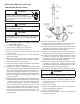
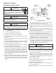
White-Rodgers 36G54 or 36J54
White-Rodgers 36G54 or 36J54
Springs and Regulator Screws