
Installation Instructions

5
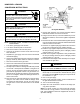
HONEYWELL VR9205Q
CONVERSION INSTRUCTIONS
CAUTION
if noX screens are present, remove as per instructions in
section “noX screen removaL.”
NOTE: For low NOx models, see table of contents for NOx
screen section.
1. Turn off the gas supply to the furnace.
2. Turn off the electrical power to the furnace.
3. Remove the furnace control access panel.
4. Check for the presence of NOx screen and remove per
NOx instruction.
5. Separate the gas supply union and remove associated
downstream piping.
6. Always use a backup wrench when removing or replacing
piping to avoid any undue strains or rotation of controls.
7. Remove the wires from the gas valve.
8. Remove the 4 sheet metal screws that fasten the manifold/
gas valve assembly to the burner box.
9. Visually inspect orices for damage and drill size (marked
on face with 1.25mm) before installation. Using the 7/16”
wrench, remove all existing natural gas orices and re-
place with the appropriate 1.25mm L.P. gas orices con-
tained in this kit. Tighten the orices to prevent gas leaks,
but do not overtighten. Retain the natural gas orices for
future reconversion.
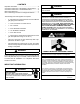
10. Remove both the inlet and outlet plugs on the gas valve,
using the 3/16” allen wrench. Install the ttings, which
accompany the manometers, into the 1/8” NPT holes of
the gas valve. Connect the manometers to the barbed
ttings.
Honeywell VR9205Q
WARNING
to prevent the possibiLity of gas Leaks, the pipe joint com-
pound or pipe thread tape must be resistant to L.p. gas.
CAUTION
to prevent unsatisfactory furnace operation, the proper
gas conversion kit must be used for the gas vaLve. use the
honeyweLL spring kit onLy with the honeyweLL gas vaLve.
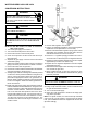
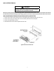
11. Remove both regulator cover screws and retain with the
Natural Gas orices for future reconversion.
12. Using a T-25 Torx driver (L Torx tool included in kit) or 3/16”
at head screwdriver, remove both regulator adjustment
screws.
13. Remove both silver colored Natural Gas regulator springs
from the regulator sleeves and retain with the Natural Gas
orices for future reconversion.
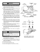
14. Insert the L.P. regulator springs (provided in the conversion
kit and color-coded red) into the regulator sleeves.
15. Install the high regulator adjustment screw provided with
the kit by threading all the way down until lightly seated
and then back off 1 1/2 turns.
16. Install the low regulator adjustment screw provided with
the kit by threading all the way down until lightly seated
and then back off 1 1/2 turns.
17. Reinstall the manifold/gas valve assembly into the appli-
ance. Rewire the gas valve.
18. Apply a liberal amount of pipe joint compound or pipe
thread tape to the threads and reassemble the piping
previously removed. NOTE: the pipe joint compound must
be resistant to L.P. gas.
19. Turn on the gas supply.
20. Using a soap and water solution, check for leaks around
the gas valve/manifold connection.
21. Turn on the electrical supply.
22. Adjust the room thermostat to obtain a rst stage (W1
only) burner operation.
NOTE: for hybrid models, the control board dip switches
need to be set to 2 stg position to set and verify rst stage
heat. (See Installation Instructions supplied with the unit for
dip switch settings)
WARNING
high voLtage!
disconnect aLL power before servicing.
muLtipLe power sources may be present. faiLure
to
do so may cause property damage, personaL
injury
or death.